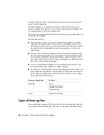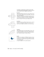
Projected View
An orthographic or isometric view that is generated from a base view
or other existing view. You can create multiple projected views in a
single operation. The position of the cursor relative to the parent view
determines the orientation of the projected view.
Projected views inherit the scale and display settings from the parent
view. Orthographic projected views keep alignment with the parent
view. The active drafting standard defines the first-angle or third-angle
projection.
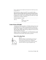
Auxiliary View
A view projected perpendicular to a user-selected line or edge. Use
Auxiliary View to document features on inclined faces.
The position of the cursor relative to the parent view determines the
orientation of the auxiliary view. Auxiliary views inherit the scale and
display settings from the parent view.
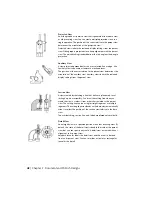
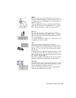
Section View
A view created by sketching a line that defines a plane used to cut
through a part or assembly. You draw the cutting line when you
create the view, or select it from a sketch associated to the parent
view. The cutting line can be a single straight segment or multiple
segments. The cutting line arrowheads on the base view automatically
orient to reflect the position of the section view relative to the base
view.
The crosshatching, section line, and labels are placed automatically.
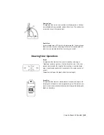
Detail View
An enlarged view of a specified portion of another drawing view. By
default, the scale of the detail view is double the scale of the parent
view, but you can specify any scale. A detail view is created without
alignment to its parent view.
Autodesk Inventor labels the detail view and the area it is derived
from on its parent view. You can set either a circular or rectangular
fence for the detail.
42 | Chapter 3 Document and Publish Designs
Summary of Contents for 466B1-05A761-1304 - AutoCAD Inventor Simulation Suite 2010
Page 1: ...Autodesk Inventor 2010 Getting Started January 2009 Part No 527B1 050000 PM01A ...
Page 6: ...vi ...
Page 60: ...54 ...
Page 80: ...74 ...


