


The MvPart exists in the drawing but is not added to a part catalog. You can add multiple instances of a
converted MvPart by copying and pasting it in a drawing. You can modify a converted MvPart by selecting
it, right-clicking, and selecting Edit MvPart Style. If you want to create an MvPart from a block, and include
it in a part catalog, use the Content Builder. For more information, see
on page 646.
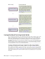
Best Practices for Creating a Block-Based Part
The following tips will help you to create a block-based part using Content Builder.
■
Do not save the source files (drawings for the 3D model and schematic symbol) in the catalog folders of
AutoCAD MEP. The source files are working files and should be saved in a separate folder.
■
To take advantage of the automatic view block creation tool in Content Builder, create the 3D model
from AutoCAD
®
solids. This also ensures support of the part in AutoCAD MEP and for rendering, shading,
and hiding in 3D model views.
■
To ensure correct display control of part sizes when added to a drawing, draw all geometry for the 3D
model and schematic symbol on layer 0. Assign BYBLOCK for color and linetype, and BYLAYER for
lineweight.
■
Assign a helpful name and description to new parts. The name specified for the part family in the New
Part dialog is used to name the files that define the part in the catalog (XML file, BMP file, DWG file).
The description is the phrase you see during part selection throughout AutoCAD MEP.
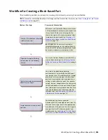
Block-Based Part Creation Overview
When you create a block-based part, you associate a pre-drawn 3D model block with basic information such
as part behavior, placement of connectors, and custom data. Block-based parts represent individual part
sizes. Using Content Builder, you define a part family and one or more part sizes. You can also create part
sizes in an existing part family. It is important to analyze the catalog hierarchy to decide the best place to
add new part families. It is also important to notice the relationships between the different part sizes you
want to create. Some may be similar in type and should belong to the same part family, while others may
be unique and require their own part family.
The following sections provide an overview for creating block-based parts using Content Builder.
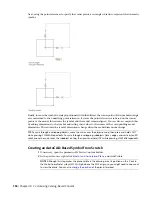
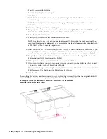
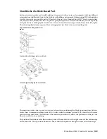
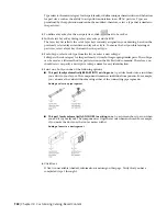
3D Model Block for a Block-Based Part
Each part size of a part family represents a real-world building systems part, such as a piece of equipment.
For each part size, you must create a 3D model block to represent the part size as it would look in the real
world. All model blocks must be created using AutoCAD
®
solids in order to support automatic generation
of view blocks, as well as rendering, shading, and hiding in 3D model views. Each 3D model block must be
saved in an AutoCAD drawing file. You can save one or more model blocks in the same drawing file.
IMPORTANT
Do not save the model block drawings in the catalog folders of AutoCAD MEP. These are working
files and should be saved in a separate, or temporary, folder.
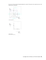
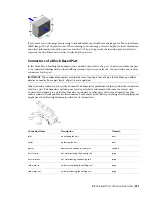
You should create the model block based on the standard AutoCAD UCS orientation to ensure that the
individual view blocks generated by Content Builder are correct. Using the SW isometric view, create the
model block at an insertion point of 0,0,0 in the world coordinate system (WCS). This ensures that each
view block generated aligns to the respective side of the model block as follows:
in the…
aligns with the…
The…
XY plane.
top side of the model block
top view block
Best Practices for Creating a Block-Based Part | 745
Summary of Contents for 235B1-05A761-1301 - AutoCAD MEP 2010
Page 1: ...AutoCAD MEP 2010 User s Guide March 2009 ...
Page 22: ...4 ...
Page 86: ...68 ...
Page 146: ...128 ...
Page 180: ...162 ...
Page 242: ...Modifying the elevation of a duct 224 Chapter 6 Drawing HVAC Systems ...
Page 264: ...246 ...
Page 480: ...462 ...
Page 534: ...516 ...
Page 616: ...598 ...
Page 658: ...640 ...
Page 788: ...770 ...
Page 802: ...784 ...
Page 820: ...802 ...
Page 878: ...860 ...