5
v3.2 (4xx26)
Programming An Option:
If you want the factory setting, DO NOTHING and skip this section. If
you want to change one or more of the features, then continue with
the following procedures:
1. Open the hood.
2. Press and HOLD the brake pedal.
3. Quickly press and release the programming button once.
4. Release the brake pedal.
The control LED will flash Red 1 time1 (signaling that you are now in
the Option Programming mode).
The LED color reflects the first option (Green LED is for Factory set-
ting, Red LED is for Optional setting).
Pressing the brake pedal advances to the next option. By continuing
to push the brake pedal, the user will advance through all of the
options and then start back at Option #1 again.
After pushing the brake pedal, the LED flashes Red (the # of the
option) before turning Red or Green, reflecting the state of the op-
tion (Green for factory setting, Red for Optional setting).
If no options are selected or changed after 6 seconds the unit will
automatically exit programming.
Push the control switch so the LED is Red, the unit is now ready.
21. Changing Ignition 2 Function
Many newer vehicles turn off the Ignition 2 wire while the starter is
cranking. In these vehicles it is very important to have the remote
starter copy the starting sequence of the key exactly; otherwise the
vehicle's computer may show a fault code or not allow the vehicle to
start at all. For most GM vehicles, you do not need to change this
option.
To turn the thick GREEN Ignition 2 wire off during crank:
1.
Unplug all wires and connections from the remote start module.
2.
Open the case of the remote start module.
3.
Look for a small two-pin jack just next to the Red programming
push button.
4.
Move the small black jumper to fit over BOTH pins on the jack.
5.
Close the case and plug in all of the wire connectors.
The remote start module will turn
OFF
Ignition 2 while the starter is
cranking. Removing the jumper will return the unit to the factory
setting.
SPECIAL CASES
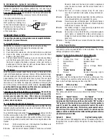
1) How to Use a Relay
Many of the optional steps require a relay to be hooked up. The most
common relay used for this type application is the Bosch type relay
(DesignTech #20043 or Radio Shack Cat.# 275-226). Use the diagram
for a typical hookup. If you have another relay then you need to know
that pins 85 and 86 in this diagram relate to the coils of the relay. Pin 30
is the ‘common’, and pin 87 is the ‘normally open’ contact. If your relay
has a pin 87A in the middle it is the normally closed contact and is only
used for lock/unlock situations. (The diagram is typical for an Ignition 3
or trunk application).
From
Remote
Starter
(-)
To Vehicle's Accessory
+12 V
87
86
85
30
To Ground
To Vehicle's Accessory
+12 V
87
86
From
Remote
Starter
(-)
85
30
+12 V
To supply Ground (-)
To 12 volt

