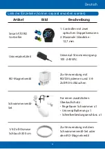
ii. Smart ATO RO
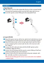
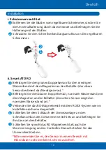
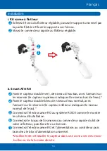
3. Mount the green sensor at the low water level (with the top sensor
indicating the low water level) on the reservoir with the magnet.
*
Mount the blue sensor at the normal water level (with the lower
4.
sensor indicating the normal water level) on the reservoir with
the magnet.
*
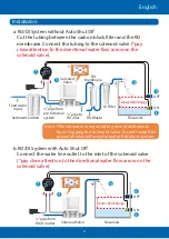
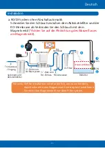
Connect the RO solenoid valve with the RO/DI system as the
5.
installation diagram shows.
Connect the RO tubing with the quick connect tting of the oat
6.
valve kit, and then x it on the reservoir.
Connect both of the RO solenoid valve and power adapter with
7.
the controller, and then connect power.
*Please avoid setting up the sensor in an area with micro bubbles
or direct light.
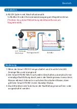
Installation
3
4
5
6
7
i. Float Valve Kit
1 Take off the nut from the adjustable oat, put the universal holder
through the threaded portion, and x the holder with the nut.
2 Screw the quick connect tting into the adjustable oat.
1
2
English
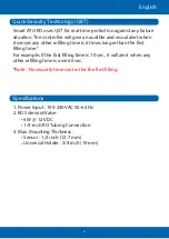
3
2
1


