background image

OM-228 305 Page 16

SECTION 5 − OPERATION

5-1.

Controls

1

4

2

3

ON

OFF

PRESSURE

60 PSI

5

6

24

27

20

16

24

27

20

16

1

24

27

20

16

Requires

90-120 PSI

(621-827 kPa)

Supply

Setting Gas/Air Pressure

1

Output Control

Use control to set cutting output.

Place control in Gas/Air Set position to safely
adjust gas/air pressure. Only gas/air circuit
is activated.

If 22-27 amperes of cutting output is used
with 115 VAC input power, and the overload
protection on the input power circuit fre-
quently opens, either reduce the cutting out-

put and/or the cut time or find more adequate
power (see Section 4-1).

2

Trouble Lights (See Section 6-2)

3

Power Light

4

Power Switch

Setting Gas/Air Pressure

5

Air Filter/Regulator

6

Pressure Adjustment Knob

Place Output control in Gas/Air position and
turn on gas/air supply. Lift knob and turn to
adjust pressure. Push knob down to lock in
setting.

Place Output control in desired cutting
output.

.

At ambient temperatures below −5

5

  C

(23

5

 F), readjustment of gas/air

pressure regulator may be necessary.

Ref. 227 835-A / Ref. 804 486-A

5

6

Set To

60 PSI (414 kPa)

Summary of Contents for Ice-27C

Page 1: ...C Torch R For Warranty Claims And Technical Support Contact Milweld Inc National Distributor P O Box 338 Hortonville WI 54944 0338 Tel 920 779 0916 Fax 920 779 0924 Processes Description Air Plasma Cutting and Gouging Air Plasma Cutter File Plasma Cutters ...

Page 2: ......

Page 3: ...bols And Definitions For Nameplate And Serial Number Rating Label 10 SECTION 4 INSTALLATION 11 4 1 Specifications 11 4 2 Specifications For Torch 11 4 3 Duty Cycle And Overheating 11 4 4 Torch Dimensions And Weight 12 4 5 Selecting A Location 12 4 6 Connecting Gas Air Supply 13 4 7 Connecting Work Clamp 14 4 8 Connecting Input Power 14 4 9 Installing Alternative Plug 15 SECTION 5 OPERATION 16 5 1 ...

Page 4: ......

Page 5: ...rs high shoes and a cap D Do not locate unit on or over combustible surfaces D Remove any combustibles such as a butane lighter or matches from your person before doing any cutting D After completion of work inspect area to ensure it is free of sparks glowing embers and flames D Use only correct fuses or circuit breakers Do not oversize or by pass them D Follow requirements in OSHA 1910 252 a 2 iv...

Page 6: ...nufacturer s instruction for metals to be cut coatings and cleaners D Work in a confined space only if it is well ventilated or while wearing an air supplied respirator Fumes from cutting and oxygen depletion can alter air quality causing injury or death Be sure the breathing air is safe D Do not cut in locations near degreasing cleaning or spraying oper ations The heat and rays of the arc can rea...

Page 7: ...ylinders or any other accessories D Use equipment of adequate capacity to lift unit D If using lift forks to move unit be sure forks are long enough to ex tend beyond opposite side of unit FIRE OR EXPLOSION hazard D Do not locate unit on over or near combustible surfaces D Do not install unit near flammables D Do not overload building wiring be sure power supply system is properly sized rated and ...

Page 8: ...Standard Z87 1 from American National Standards Institute 25 West 43rd Street New York NY 10036 8002 phone 212 642 4900 website www ansi org Standard for Fire Prevention During Welding Cutting and Other Hot Work NFPA Standard 51B from National Fire Protection Association P O Box 9101 Quincy MA 02269 9101 phone 617 770 3000 web site www nfpa org OSHA Occupational Safety and Health Standards for Gen...

Page 9: ... coupez pas sur un contenant fermé tel qu un réservoir ou un bi don D Fixez le câble de masse sur la pièce à couper le plus près possible de la zone à couper afin de prévenir que le courant de coupage ne prenne une trajectoire inconnue ou longue et ne cause ainsi une décharge électrique d étincelles ou un feu D Ne pas utiliser le coupeur plasma pour dégeler des conduites ge lées D Ne coupez jamais...

Page 10: ...s la téraux approuvées D Portez des vêtements de protection adéquats afin de protéger vo tre peau D Ayez recours à des protège tympans ou à un serre tête ignifuges afin d éviter que les étincelles n entrent dans vos oreilles Les rayons d arc provenant du procédé de coupage produisent des rayons visibles et invisibles intenses ultraviolets et infrarouges qui peuvent entraîner des brûlures aux yeux ...

Page 11: ...act électrique ne doit jamais se produire entre un chalu meau de plasma d arc et une bouteille D Ne coupez jamais sur une bouteille pressurisée une explosion en résulterait D Utilisez uniquement des bouteilles de gaz des détendeurs des boyaux et des raccords conçus pour l application déterminée Gar dez les ainsi que toute autre pièce associée en bonne condition D Détournez votre visage du détendeu...

Page 12: ...ièrement le contrôle et l entretien de l installation D Maintenir soigneusement fermés les portes et les panneaux des sources de haute fréquence maintenir les éclateurs à une distan ce correcte et utiliser une terre et et un blindage pour réduire les interférences éventuelles LE COUPAGE Ã L ARC peut causer des interférence D L énergie électromagnétique peut gêner le fonctionnement d appareils élec...

Page 13: ... and Part 1926 Subpart J de U S Government Printing Office Superinten dent of Documents P O Box 371954 Pittsburgh PA 15250 7954 téléphone 1 866 512 1800 il y a 10 bureaux régionaux le télépho ne de la région 5 Chicago est 312 353 2220 site Internet www osha gov 2 6 Information EMF Considérationssur le soudage et les effets de basse fréquence et des champs magnétiques et électriques Le courant de s...

Page 14: ...rrent Voltage Input On Off Percent Direct Current U0 Rated No Load Voltage Average U1 Primary Voltage U2 Conventional Load Voltage Line Connection I1max Rated Maximum Supply Current I2 Rated Welding Current X Duty Cycle 1 f1 f2 Single Phase Static Frequency Transformer Rectifier Converter IP Degree Of Protection Loose Shield Cup Input Hz Hertz I1eff Maximum Effective Supply Current pf power factor...

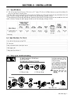
Page 15: ...lasma Gas Plasma Gas Flow Pressure Cutting Capacity at 10 IPM Max OCV 27 A at 92 Volts DC At 35 Duty Cycle 28 max 0 30 14 max 0 13 3 32 KVA 3 25 KW 3 25 KVA 3 19 KW Air Or Nitrogen Only 4 5 CFM 129 L min At 60 PSI 414 kPa 3 8 in 10 mm 288 Volts DC While idling 4 2 Specifications For Torch Air cooled torch for plasma arc cutting PAC 35 duty cycle Safety interlock devices shut down power source Safe...

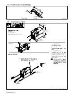
Page 16: ...put power a customer supplied plug is necessary see Section 4 9 Locate unit near correct input power supply Special installation may be required where gasoline or volatile liquids are present see NEC Article 511 or CEC Section 20 Movement Location And Airflow Dimensions And Weight 49 lb 22 2 kg not including torch Add 13 16 in 21 mm for handle 16 in 406 mm 8 1 2 in 216 mm 12 5 16 in 313 mm 1 2 10 ...

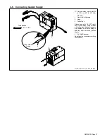
Page 17: ...ssure 1 Gas Air Inlet Opening 2 Hose 3 Teflon Tape Obtain hose with 1 4 NPT right hand thread fitting Wrap threads with teflon tape optional or apply pipe sealant and install fitting in opening Route hose to gas air supply 4 Air Filter Regulator Adjust gas air pressure according to Section 5 1 Tools Needed 5 8 1 1 8 in 3 1 2 From Gas Air Supply 4 ...

Page 18: ...ective eff current for the output being used The unit must have a properly sized plug installed and the circuit must be protected by properly sized fuses or cir cuit breakers A 120 volt 20 ampere individual branch circuit protected by time delay fuses or circuit breaker is required see Section 4 1 4 Plug From Unit Connect plug to receptacle If an extension cord is necessary select a cord of 12 AWG...

Page 19: ...s Strip conduc tors enough to make good contact with plug terminals Make plug con nections and reinstall outer shell and cord grip Tighten assembly screws onto shell Do not overtighten Ref 801 305 A 801 611 This procedure is necessary if the unit is to be connected to a 230 VAC receptacle or to a 115 VAC receptacle that requires a plug that is different from the supplied plug Tools Needed 1 6 7 2 ...

Page 20: ...protection on the input power circuit fre quently opens either reduce the cutting out put and or the cut time or find more adequate power see Section 4 1 2 Trouble Lights See Section 6 2 3 Power Light 4 Power Switch Setting Gas Air Pressure 5 Air Filter Regulator 6 Pressure Adjustment Knob Place Output control in Gas Air position and turn on gas air supply Lift knob and turn to adjust pressure Pus...

Page 21: ... Aluminum and Stainless Steel cut speeds at these thicknesses may be reduced as much as 20 Recommended Cut Speeds At 20 Amperes Output Thickness Recommended Cut Speeds Inches mm ipm mm min Mild Steel 16 ga 1 5 162 4 115 Mild Steel 3 16 4 8 26 660 1 4 6 4 18 457 3 8 9 5 7 178 Recommended Cut Speed is approximately 80 of maximum Aluminum and Stainless Steel cut speeds at these thicknesses may be red...

Page 22: ...tting Operation Raise trigger lock and press trigger Pilot arc starts Postflow continues for 20 seconds after releasing trigger cutting arc can be instantly restarted during postflow by raising trigger lock and pressing trigger The pilot arc starts immediately when trigger is pressed Place tip on work for drag cutting or for maximum cutting speed and tip life use a standoff distance of 1 16 in 1 6...

Page 23: ...o be done by Factory Authorized Service Agent Reference Each Use Section 4 6 6 4 Use n Gas Air Pressure n Torch Tip Electrode And Shield Cup 6 4 Every Week Section 6 2 Week n Shield Cup Shutdown System Section 6 2 Every 3 Months l Damaged Or Unreadable Labels Air Filter Regulator l Cracked Parts n l Gas Air Hose Section 8 Months Section 8 n l Torch Body Cable Every 6 Months OR Months Inside Unit ...

Page 24: ...at the torch consumables are stuck or worn and should be inspected and or replaced see Section 6 4 Check shield cup shutdown system once a week 3 Temperature Light Lights if power source overheats or when ambient temperature is below 35 C 31 F see Section 4 3 4 Torch Shield Cup Turn Power On and loosen shield cup If shutdown system works properly Ready light goes off and Cup light comes on If not ...

Page 25: ...d to circuit board PC1 5 Ring Terminal And TORCH RED Terminal Connect ring terminal on end of red leads to TORCH RED terminal 6 Ring Terminal And TORCH WHITE Terminal Connect ring terminal on end of white leads to TORCH WHITE terminal Tighten strain relief nut Tighten strain relief around cable Work Cable Connections Remove existing work cable from unit 7 Work Cable Be sure to allow some work cabl...

Page 26: ... place shield cup if necessary 3 Tip 4 Opening Remove tip Check tip and replace if open ing is deformed or 50 oversize If inside of tip is not clean and bright clean with steel wool Be sure to remove any pieces of steel wool afterwards 5 Electrode Check electrode If center has a pit more than a 1 16 in 2 mm deep remove and re place electrode 6 Swirl Ring 7 O Ring Remove swirl ring Check ring and r...

Page 27: ...e Status light On or flashing Press torch trigger and check if pilot arc ignites Check torch consumables Check torch connections air filter pressure switch S3 valve AS1 air supply connection to unit torch and PC1 Yes No Does pilot arc ignite Place torch near workpiece and check if pilot arc jumps or transfers to workpiece Check work clamp connection Check Control board PC1 and connections and torc...

Page 28: ...lace torch consumables as necessary see Section 6 4 Do sparks come out of top of cut or cut is not clean No Yes Torch travel speed too fast reduce travel speed see Section 4 1 Clean or replace torch consumables as necessary see Section 6 4 Be sure work clamp is securely attached to workpiece Unit not capable of cutting metals thicker than rating see Section 4 1 Is Trouble light On unit has no cutt...

Page 29: ...OM 228 305 Page 25 SECTION 7 ELECTRICAL DIAGRAM Figure 7 1 Circuit Diagram 227 893 A ...

Page 30: ...OM 228 305 Page 26 SECTION 8 PARTS LIST Hardware is common and not available unless listed 804 490 B 13 18 16 4 5 1 2 26 6 25 24 22 20 19 21 7 8 9 10 11 12 15 23 3 17 14 Figure 8 1 Main Assembly ...

Page 31: ...ding 1 206 000 VALVE 24VDC 3 way 1 8NPT 1 227 840 FILTER air w drain ftgs 1 227 877 FILTER air element 1 200 728 BRACKET mtg air filter 1 17 227 865 BAFFLE center 1 18 PC1 234 264 CIRCUIT CARD ASSY control w pgm 1 19 227 832 REGULATOR air w fittings switch 1 S3 227 843 SWITCH pressure 1 228 425 REGULATOR air 1 20 195 014 ICE 27C 20ft hand held including 1 121 276 BUSHING strain relief 1 21 200 517...

Page 32: ...Grease silicone 1 195 014 Torch replacement 20ft 1 See Figure 8 3 for additional consumable parts 1 1 2 3 4 5 Item No Part No Description Figure 8 2 Torch ICE 27C 203 492 Figure 8 3 Consumable Parts For ICE 27C To maintain the factory original performance of your equipment use only Manufacturer s Suggested Replacement Parts Model and serial number required when ordering parts from your local distr...

Page 33: ...Notes ...

Page 34: ...Notes ...

Page 35: ...nents such as contact tips cutting nozzles contactors relays brushes slip rings or parts that fail due to normal wear 2 Items furnished by manufacturer but manufactured by others such as engines or trade accessories These items are covered by the manufacturer s warranty if any 3 Equipment that has been modified by any party other than manufacturer or equipment that has been improperly installed im...

Page 36: ...Serial Style Number Contact your Distributor for Welding Supplies and Consumables Options and Accessories Personal Safety Equipment Service and Repair Replacement Parts Owner s Manuals Circuit Diagrams Contact the Delivering Carrier to Resources Available Owner s Record File a claim for loss or damage during shipment For assistance in filing or settling claims contact your distributor and or equip...

Reviews: