27
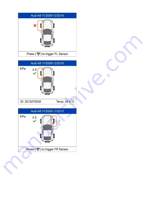
Sensor activation failed.
Sensor activation successful.
Sensor ID displays on the left side of the bottom bar and the temperature displays on the right side of the bottom bar.
D
icon indicates that a duplicate
sensor ID has been read.
Page 1: ...at the time of printing Autel reserves the right to make changes at any time without notice While information of this manual has been carefully checked for accuracy no guarantee is given for the completeness and accuracy of the contents including but not limited to the product specifications functions and illustrations Autel will not be liable for any direct damages or for any special incidental o...
Page 2: ...methods and test procedures It is essential to perform tests in an appropriate and acceptable manner that does not endanger your safety the safety of others in the work area the device being used or the vehicle being tested Before using the device always refer to and follow the safety messages and applicable test procedures provided by the manufacturer of the vehicle or equipment being tested Use ...
Page 3: ...he ignition coil distributor cap ignition wires and spark plugs These components create hazardous voltages when the engine is running Keep a fire extinguisher suitable for gasoline chemical electrical fires nearby Put the transmission in PARK for automatic transmission or NEUTRAL for manual transmission and make sure the parking brake is engaged Always turn the ignition off before connecting disco...
Page 4: ...8 VEHICLE IDENTIFICATION 8 SCAN SENSOR 10 PROGRAM SENSOR 12 RELEARN PROCEDURE 20 SENSOR INFORMATION 21 4 TPMS ADVANCED MODE 23 VEHICLE IDENTIFICATION 23 TPMS DIAGNOSE 25 PROGRAM SENSOR 31 POSITION RELEARN 43 INFORMATION 49 TIRE TYPE PRESSURE SELECTION 51 5 MISCELLANEOUS 54 TOOLKIT 54 LATEST TEST 55 REVIEW DATA 55 MY DEVICE 55 PRINT 71 PRODUCT TROUBLESHOOTING 72 6 COMPLIANCE INFORMATION 74 ...
Page 5: ...v 7 WARRANTY AND SERVICE 76 LIMITED ONE YEAR WARRANTY 76 SERVICE AND SUPPORT 77 ...
Page 6: ...ility of other modules and optional tools or accessories Conventions The following conventions are used Bold Text Bold text is used to highlight selectable items such as buttons and menu options Example Tap OK Notes and Important Messages Notes A NOTE provides helpful information such as additional explanations tips and comments Example NOTE New batteries reach full capacity after approximately 3 ...
Page 7: ...nks or links that take you to other related articles procedures and illustrations are active in electronic documents Blue italic text indicates a selectable hyperlink and blue underlined text indicates a website link or an email address link Illustrations Illustrations used in this manual are samples and the actual testing screen may vary for each vehicle being tested Observe the menu titles and o...
Page 8: ...holds the MX Sensor to be programmed 2 LCD DISPLAY displays the menus and test screens 3 N BUTTON cancels a selection or action from a menu or return to previous menu 4 UP SCROLL BUTTON moves up through menu and submenu items in menu mode When more than one set of data are retrieved use ...
Page 9: ...rt press the button to return to Home screen 9 RIGHT SCROLL BUTTON when scrolling through a screen of data or text moves to next character and view additional information on next screens if recorded data content covers more than one screen 10 TEST BUTTON commences a TPMS Test or confirms selections on screen 11 Y BUTTON confirms a selection or action from a menu 12 USB PORT connects the TPMS tool ...
Page 10: ...shed 5 indicates magnet is required to activate TPMS sensor 6 indicates deflation is required to activate TPMS sensor 7 indicates wheels will be checked one by one 8 indicates the TPMS tool is sending signals to the tire sensor for activation and test in activation screen or indicates the sensor information is read by activation 9 indicates the tool communication with the vehicle s OBD II DLC is e...
Page 11: ...he tool for at least 2 hours before the first use NOTE Only use the USB cable adapter included in our pack to charge this tool The use of unapproved power supplies may damage your tool and void the tool warranty Power up by DLC The tool can also be powered by the vehicle via OBD II cable connection to the vehicle Data Link Connector DLC Just follow the steps below to turn on the TPMS tool 1 Connec...
Page 12: ...7 Figure 2 2 Sample Main Menu Screen NOTE OBD II cable connection does not support battery charging ...
Page 13: ...e Perform basic TPMS functions through the Quick service mode Scan Sensor Program Sensor Relearn Procedure and Sensor Information Confirm Select test vehicle to start a TPMS service session Vehicle Identification Confirm ...
Page 14: ...9 Select by Model Confirm Select by Year 1 For vehicles using indirect TPMS Confirm Follow the instructions displayed to perform Relearn for indirect TPMS ...
Page 15: ...TPMS Confirm Functions provided in Quick Mode Scan Sensor Program Sensor Relearn Procedure and Sensor Information Scan Sensor Hold the tool close to the sensor or close to the tire sidewall right above the sensor 1 For first time use ...
Page 16: ...11 Press Y or Trigger to trigger the sensor The device is receiving data from the sensor Trigger Successful The ID pressure temperature and voltage of the sensor display on screen ...
Page 17: ... or Trigger to try again Program Sensor Copy by Activation This function is used to activate or trigger the original sensor and retrieve the ID of the sensor and then write the original sensor ID into the new MX Sensor ...
Page 18: ...is still attached to the wheel hold the tool close to the tire sidewall right above the sensor Confirm Press Y or Trigger to trigger the sensor Trigger Succeessful Original sensor ID displays on the screen Press Trigger to trigger again and press Y to program the original sensor ID into MX Sensor ...
Page 19: ...gger failed Press Y or Trigger to try again Place a new MX Sensor in the sensor slot or hold the top of the tool close to the sensor to program Sensor Programming The programming function automatically begins ...
Page 20: ...ls to program Press any key to continue Ensure a MX Sensor with the correct frequency is used Try to program sensor again The number in the brackets indicates the fault code it can be used for Autel technicians to quickly identify the fault No sensor detected Ensure the unit software is up to date ...
Page 21: ...put This function is used to manually input the original sensor ID and program it to new MX Sensor Confirm Press Trigger to select the numbers press N to exit and once a number is selected the N button can be used to delete the entered number After all the numbers are entered press Y to confirm ...
Page 22: ...17 Exit Confirm and Program Sensor Programming The programming function automatically begins Once programmed sensor and tire data will display ...
Page 23: ...Sensor with the correct frequency is used Try to program sensor again No sensor detected Ensure the unit software is up to date Multiple sensor detected Ensure that only one sensor is close to the tool Auto Create 1 16 Sensors This function is used to auto create new unique ID s into 1 16 MX Sensor s ...
Page 24: ...19 Place 1 16 MX Sensor s close to the top of the tool The tool will automatically detect the sensors near the tool Cancel Continue ...
Page 25: ...ce the sensors are successfully programmed the sensor IDs and the PSNs Product Serial Number will display on the tool Relearn Procedure Confirm Read the Relearn Procedure carefully to complete the operation ...
Page 26: ...21 Sensor Information Confirm MX Sensor Information Place a MX Sensor near the top of the tool and then press Y Confirm ...
Page 27: ...the code used to identify the area of your tool for Autel Support when you file a problem report OE Sensor Information Confirm The tool will automatically display the information of the OE sensor mounted on the test vehicle ...
Page 28: ...anced service mode performs additional TPMS functions TPMS Diagnose Program Sensor Position Relearn and Information OE and MX Sensor data and vehicle OBDII port location diagram Vehicle Identification Confirm Select by Model Confirm ...
Page 29: ...24 Select by Year 1 For vehicles using indirect TPMS Confirm Follow the Relearn procedure displayed for vehicles with indirect TPMS 2 For vehicles using direct TPMS Confirm ...
Page 30: ...nformation For some vehicle a fifth option Tire Type Pressure Section is available TPMS Diagnose This function is used to check TPMS and sensor status Confirm The TPMS Diagnose Guide will display if sensor activation is not performed before Press any key to turn to the sensor activation menu ...
Page 31: ...n menu and reactivate one sensor then the tool will prompt you to connect OBD cable for ECU diagnosis or press Yes to clear the previous data and reactivate the sensors Trigger Activate Sensors Follow the onscreen instructions to activate all the sensors mounted on the test vehicle Press Trigger to activate the sensor The tool is receiving data from the sensor ...
Page 32: ...tion failed Sensor activation successful Sensor ID displays on the left side of the bottom bar and the temperature displays on the right side of the bottom bar D icon indicates that a duplicate sensor ID has been read ...
Page 33: ...ctions to connect the tool with the test vehicle via OBD II cable Turn on the ignition Press N to show the Sensor Status or press Y to continue and the tool will automatically read the sensor IDs and Data Trouble Codes DTCs present in the ECU The Sensor Status screen displays position sensor ID tire pressure tire temperature and battery level of the activated sensors ...
Page 34: ... ECU ID matches Sensor ID Red signal and OBDII icons the ECU ID does not match Sensor ID Red battery icon low sensor battery Amber TPMS icon DTC s present in the ECU Press Y to view sensors data Positions activated sensor IDs and ECU registered IDs display on the screen Use and to view more information ...
Page 35: ... temperature and battery level display on the second page Press N to exit Use Up and Down Arrow button to select the TPMS icon in the center of the graphed vehicle and press Y to view the DTCs Back Erase DTC Save ...
Page 36: ...ss The tool will automatically re check the ECU to ensure all DTCs have been deleted If no DTC s is present in the ECU the middle TPMS icon displays gray and a No DTCs message displays at the right bottom of the screen Program Sensor Confirm ...
Page 37: ...or Press Y to confirm selection If no TPMS diagnosis is performed before the tool will prompt the user to connect OBD cable and then read information from the ECU If TPMS diagnosis is performed then the next screen displays Press Y to use the previously stored data and then the sensor IDs saved in the ECU displays or press N to use new data and then the following screens display ...
Page 38: ...cle via the OBD II cable Press Y to continue or press N to exit The tool will automatically read data from the ECU The sensor IDs saved in the ECU display on the screen Place one MX Sensor near the top of the tool Select one sensor ID and press Y to program the new MX Sensor ...
Page 39: ...No sensor detected Press any button to continue Multiple sensors detected Place one sensor close to tool and press any key to continue One sensor is detected The programming function automatically proceeds ...
Page 40: ...new MX Sensor There is no need to perform the Relearn function to write the ID into the ECU when the new programmed sensor has been put in the same position The Copy by OBD programming method if available is recommended to program new MX Sensors as there is no need for Relearn Copy by Activation This function is used to activate the original sensor and retrieve the ID of the sensor and then progra...
Page 41: ...tion from programming list Activate or Trigger sensor to be copied Trigger successful Original sensor ID displays on screen Press Y to program the original sensor ID to MX Sensor Trigger failed Press Y or Trigger to try again ...
Page 42: ...7 Place a new MX Sensor near the top of the tool to program No sensor detected Press any button to continue Multiple sensor detected Place one sensor close to top of tool and press any button to continue ...
Page 43: ...g Failed Press any key to continue By using Copy by Activation the sensor ID that is retrieved from activated sensor is programmed to the new MX Sensor Because the ID of the original sensor and the new MX Sensor are the same and the ID is already registered to the vehicle ECU there is no need to perform the Relearn function when the new programmed sensor has been attached to the same wheel ...
Page 44: ...iginal sensor ID and program it to a new MX Sensor Confirm Press Trigger to select the numbers press N to exit and once a number is selected the N button can be used to delete the entered number After all the numbers are entered press Y to confirm Exit Confirm and Program ...
Page 45: ...nsor detected Press any button to continue Multiple sensors detected Place one sensor close to top of tool and press any button to continue One sensor is detected The programming function automatically proceeds ...
Page 46: ...or that is already stored within the TPMS ECU and therefore does not require the sensor be relearned if the new programmed sensor has been put in the same wheel location Auto Create 1 16 Sensors This function is used to auto create unique ID s to 1 16 MX Sensor s A random ID will be created for the MX Sensor This new ID differs from the ID stored in the TPMS ECU therefore the sensor will have to b...
Page 47: ...42 Place 1 16 MX Sensor s close to the top of the tool The tool will automatically detect the sensors near the tool Cancel Continue ...
Page 48: ... and the PSNs will display on the tool Position Relearn Generally speaking there are three ways for position relearn Stationary Relearn Automatic Relearn and OBD Relearn Stationary Relearn Stationary Relearn requires the vehicle be placed in the Learn Mode Confirm ...
Page 49: ...ote all the sensors should be successfully activated without any duplicated IDs Once all sensors are successfully activated then follow the Relearn Procedure to perform Stationary Relearn Automatic Relearn For some vehicles the Relearn function can be completed by driving Refer to the on screen Relearn Procedure for the exact details of the process ...
Page 50: ...form Relearn activate sensors on FL FR RR and RL wheels If there is sensor triggered the tool will ask whether to clear the saved data press N to use the saved data and reactivate one sensor the tool will instruct you to connect OBD cable and then perform OBD Relearn or press Y to clear the data and display the Relearn Procedure The Relearn Procedure displays when no sensor is triggered ...
Page 51: ...formed before follow the onscreen instructions to activate all the sensors mounted on the vehicle Note all the sensors should be successfully activated without any duplicated IDs Once all sensors are successfully activated the tool will prompt users to perform OBD Relearn if supported by the vehicle ...
Page 52: ... the onscreen instructions to connect the tool and vehicle via OBD cable and turn the ignition on Press Y to continue The tool is writing sensor ID to ECU please wait OBD Relearn Failed Press any key to continue ...
Page 53: ...earn Successful The sensor IDs have been written to the ECU and the tool will automatically erase the DTCs present in the ECU When all DTCs have been deleted the TPMS icon displays gray Press any key to continue ...
Page 54: ...49 Information MX Sensor Information Place a MX Sensor near the top of the tool and press Y to continue ...
Page 55: ...50 OE Sensor Information Confirm The tool will display the information of the OE sensor for the selected vehicle OBD Location ...
Page 56: ...acard but the TPMS MIL is still on you may need to use this function to select your tire type and set the right tire pressure value Read Tire Type Pressure Select Read Tire Type Pressure and press Y to read the tire type and pressure of the test vehicle Press Save to save the reading for later review or press Back to exit without saving ...
Page 57: ...hange and press Trigger to enter the edit menu Take Front Tire Type as an example Use the UP DOWN button to select the correct tire type and press Y to confirm and exit Move to the next item Front Tire Pressure on Placard and press the Trigger button to edit ...
Page 58: ...N button to select the correct tire pressure on placard and press Y to confirm and turn to the previous menu After all the changes are completed press Y to confirm and exit or press N to exit without saving the changes ...
Page 59: ... from the Main Menu and press the Y button to confirm Figure 5 1 Sample ToolKit Selection Screen 2 The screen displays as below select RKE RF Monitor and press Y to confirm test strength of remoteless key fob Figure 5 2 Sample RKE RF Monitor Menu 3 Hold the key fob close to the tool and press the function buttons on key ...
Page 60: ...r the beep tone The tool tests only 315MHz and 433MHz key fobs 4 Select Unlock ECU just support Toyota and follow the onscreen instructions to unlock the ECU on Toyota vehicles Latest Test The Latest Test function saves the route of the last test User can select this function to quick access the last test record and proceed testing Review Data The Review Data function enables users to view and pri...
Page 61: ... USB with the Maxi PC Suite The update procedures for the Mac and Windows versions of the Maxi PC Suite are the same and the Windows version is taken as an example here Connect the tool to a Windows based computer using the supplied USB cable power on the tool Follow the update procedure to finish updating 1 Download the Maxi PC Suite from www maxitpms com Product MaxiTPMS TS508WF Downloads and in...
Page 62: ...inder 5 Enter your email address to register click Next to continue 6 If you haven t registered before a captcha will be sent to your email address input your password and the captcha you received and then click Sign Up to register the connected device If the connected device has already been registered the Maxi PC Suite will turn to the Update menu directly If you have registered before input you...
Page 63: ...58 Figure 5 7 Sample Registration Reminder Figure 5 8 Sample Registration Dialog Box 7 On the Updates Available page select the appropriate files to install ...
Page 64: ...led automatically and will replace the older version Figure 5 10 Sample Program Update End Update by Wi Fi The scan tool needs to be connected with the USB cable during updating via Wi Fi follow the update procedures to finish updating 1 Open the device select Update by Wi Fi on the My Device Menu ...
Page 65: ...Fi to directly connect to the same Wi Fi after the first scanning and connecting Figure 5 12 Sample Update by Wi Fi Menu 3 The device will automatically detect whether it s bound to an Autel ID after connected to Wi Fi successfully 4 If you haven t an Autel ID and the device has not been bound input your email address as your Autel ID ...
Page 66: ...erification code Input the verification code and create an Autel ID password on the tool In this way you ve registered an Autel ID meanwhile the device is bound to this ID Update information will be scanned automatically Figure 5 14 Sample Note Screen Figure 5 15 Sample Note Screen ...
Page 67: ...fully bound update information will be scanned automatically Figure 5 16 Sample Input Autel ID Screen Figure 5 17 Sample Input Password Screen 7 If the device software needs to be updated proceed as information displayed on the screen Connect the device to the USB cable press Y button updating starts automatically ...
Page 68: ...ice to it on your website http pro autel com or do it on the Maxi PC Suite 8 The device will restart automatically after update successfully View or Delete Programs To view the list of installed programs or to delete an installed program please follow these steps 1 Click on the Installed tag entry and the list of installed programs displays 2 Select the program s that you would delete ...
Page 69: ...ake the following adjustments and settings 1 Market Selects the operating region of the tool 2 Language Selects the operating language of the tool 3 ID Format Sets the ID display to Hexadecimal Decimal or Auto 4 Pressure Unit Sets the pressure unit in kPa Psi or Bar 5 Temperature Unit Sets the temperature unit in degrees to Celsius or Fahrenheit 6 Distance Unit Sets the distance unit in km or mile...
Page 70: ...ow Figure 5 20 Sample System Setup Screen Market TIPS The default market selection depends on the area the tool is sold 1 From System Setup screen use the UP DOWN scroll button to select Market and press the Y button 2 Use the LEFT RIGHT scroll button to select the desired market or tool operating region and press the Y button to save your selection and return to previous menu ...
Page 71: ...utton 2 Use the UP DOWN scroll button to select the desired language and press the Y button to save your selection and return to previous menu Figure 5 22 Sample Language Selection Screen ID Format 1 From System Setup screen use the UP DOWN scroll button to select ID Format and press the Y button 2 From ID Format screen use the LEFT RIGHT scroll button to select the desired ID format ...
Page 72: ...o select Pressure Unit and press the Y button 2 From Pressure Unit screen use the LEFT RIGHT scroll button to select the desired unit kPa Psi or Bar Figure 5 24 Sample Pressure Unit Screen 3 Press the Y button to save your settings and return to previous menu or press the N button to exit without change Temperature Unit 1 From System Setup screen use the UP DOWN scroll button to select Temperature...
Page 73: ...s the N button to exit without change Distance Unit 1 From System Setup screen use the UP DOWN scroll button to select Distance Unit and press the Y button 2 From Distance Unit screen use the LEFT RIGHT scroll button to select the desired unit of distance km or mile Figure 5 26 Sample Distance Unit Screen 3 Press the Y button to save your settings and return to previous menu or press the N button ...
Page 74: ... turn on off the beep Figure 5 27 Sample Beep Set Screen 3 Press the Y button to save your selection or the N button to exit without change Power off 1 From System Setup screen use the UP DOWN scroll button to select Power off and press the Y button 2 Press UP DOWN scroll button to increase or decrease the amount of time of inactivity before the tool automatically powers off Press the Y button to ...
Page 75: ... and Time This function sets time and date on tool 1 From System Setup screen use UP DOWN scroll button to select Date and Time and press the Y button to confirm wait for the Date and Time screen to display 2 Use UP DOWN scroll button to increase or decrease the value and LEFT RIGHT scroll button to select the item to change Figure 5 29 Sample Date and Time Screen About This function allows viewin...
Page 76: ...rs for the present 1 Download the Maxi PC Suite from www maxitpms com Product MaxiTPMS TS508WF Downloads and install it onto your computer 2 Connect the tool to the computer with the supplied USB cable 3 Run Autel Printer software on computer 4 Select Review Data function in Main Screen of the TPMS tool In data menu screen use the UP DOWN scroll button to select the data you want to print Wait for...
Page 77: ...lipboard Clear delete data in the textbox Exit quit the operation Product Troubleshooting This part describes problems that you may encounter while using the TPMS tool Vehicle Linking Error A communication error occurs if the TPMS tool fails to communicate with the vehicle s ECU Electronic Control Unit when running the diagnostic function You need to do the following to check up Verify that the ig...
Page 78: ...ff and wait for about 10 seconds Turn the ignition back on and continue testing Verify the control module is not defective Operating Error If the scan tool freezes reset the tool Turn the ignition off and wait for about 10 seconds Turn the ignition back on and continue testing ...
Page 79: ...t expressly approved by the party responsible for compliance could void the user s authority to operate the equipment NOTE This equipment has been tested and found to comply with the limits for a Class B digital device pursuant to Part 15 of the FCC Rules These limits are designed to provide reasonable protection against harmful interference in a residential installation This equipment generates u...
Page 80: ...equipment RF WARNING STATEMENT The device has been evaluated to meet general RF exposure requirement The device can be used in portable exposure condition without restriction The term IC before the radio certification number only signifies that IC technical specifications were met RoHS COMPLIANCE This device is declared to be in compliance with the European RoHS Directive 2011 65 EU CE COMPLIANCE ...
Page 81: ...ounting of the device Some states do not allow limitation on how long an implied warranty lasts so the above limitations may not apply to you This warranty does not apply to 1 Products subjected to abnormal use or conditions accident mishandling neglect unauthorized alteration misuse improper installation or repair or improper storage 2 Products whose mechanical serial number or electronic serial ...
Page 82: ... maxitpms com Email ussupport autel com Address 175 Central Avenue Suite 200 Farmingdale New York USA 11735 AUTEL EUROPE Phone 0049 0 61032000522 Website www autel eu www maxitpms com Email sales eu autel com support eu autel com Address Robert Bosch Strasse 25 63225 Langen Germany AUTEL CHINA HQ Phone 0086 755 22672493 86532091 Website www autel com www maxitpms com Email supporttpms auteltech co...
Page 83: ... PanamáPací fico Panamá AUTEL AUSTRALIA Phone 03 9480 2978 61 476293327 Website www autel com au www maxitpms com Email sales autel com au Address 155 Islington Street Melbourne Collingwood VIC For technical assistance in other markets please contact your local distributor ...