USER MANUAL
Scissor
ASLP-3005
ASLP-3005/IG
ISSUED 04-02-2004
AUTEC Hefbruggen bv
Industrieterrein Ijsselveld, Vlasakker 11, 3417 XT MONTFOORT, The Netherlands
Tel:+31 348 477000 Fax:+31 348 475104 E-mail: [email protected]
MAIN SWITCH (7)
Position 0 :
In this position, the lift is no
longer live, if necessary, a lock may be
placed on the main switch, so as to
prevent unauthorised access or
operation of the lift.
Position 1 :
When the
main switch
is
in the position “1”, the electric circuit
becomes live.
EMERGENCY STOP BUTTON (4)
Take care to see that this is fully in the
off position. If this is pressed, it is not
possible to run the lift.
LIFTING MOTION BUTTON (6)
On pressing this button, the motor and
the lifting motion valve become live, and
the lift will rise.
LOWERING MOTION BUTTON (5)
On pressing this button, the lowering
motion valves will become live, and the
lift will fall to the safety height of 400
mm from the ground.
SAFETY BUTTON FOR DOWNWARD
MOVEMENT (7)
On pressing this button, the horn, and
after a few seconds, the valves must
become live. The lift will now complete
the last 400 mm of the downward
movement. And the lift will
simultaneously synchronise once it
reaches the lowest position.
SEQUENCE OF OPERATIONS
•
Positioning of the vehicle
Park the vehicle in the middle of the
platform and if necessary push out
the extension pieces of the platform.
•
Support points
Place the rubber supports under the
car-jack support points of the
vehicle.
•
Lifting
Set the main switch
(7)
in position 1
and if necessary, turn the
emergency stop button in the proper
position. Press the lifting button
(6)
until the desired height is reached.
The lift will now stop automatically.
•
Lowering
Press the switch for the lowering motion
(5).
The lift will now sink to 400 mm above the
ground. Check whether the safety area under and around the lift is free of personnel and
obstacles of any kind. Now let the lift sink lower by pressing the safety button for the
lowering action
(1)
.
•
Emergency Lowering
If there is a power failure, one can lower the lift in the following manner :
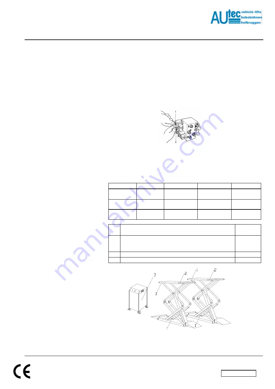
1. In the control cabinet, the two lowering-motion valves
(Fig. 18)
must be
simultaneously opened by turning them in the anti-clockwise direction.
2. When the platform has been lowered completely, the valves must be closed tight
after the platform has been fully lowered.
Fig. 18
7. MAINTENANCE
The lift must be inspected once a year according to the CE Regulations, by a person who
is certified to do the same. In addition, preventive maintenance must also be carried out
once a year on the lift (ask for AUTEC maintenance contracts).
We recommend the following lubricants for lubricating the lift (see Fig. 19) :
No.
Texaco
Shell
ESSO
Castrol
1. Guides
Teflon spray
Teflon spray
Teflon spray
Teflon spray
2. Guide
support plates
Molytex EP 2
Alvania HDX vet 2
Multipurpose vet +
moly
MS3 grease
3. Hydraulic
system
Rando 32
Tellus 32
Nutto H32
HYSPIN HWS
32
No.
Lubricating points
Lubricating
interval
1. Guides for the sliding block (only lubricate the guides on the upper
side of the guide blocks. Do not lubricate the underside, because
this accumulates dirt).
3 months
2. Guides for the support plate extension pieces
3 months
3. Replacement of hydraulic oil
5 years
Fig. 19
en/TA-ASLP-3005-06


