AE50R, AE50RA
AE50RAB
Engine Manual
Doc. No. E1.01.0-E
Rev. 6 10-March-2011
Page 18-6
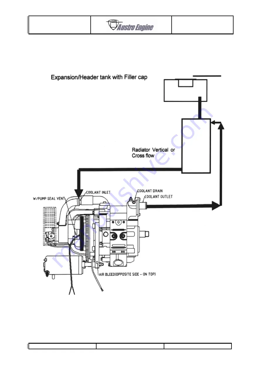
18.3.4 Cooling Circuit Schematic
Typical Cooling Circuit
Fig.
10
Page 1: ...ntained in this document has been approved under the authority of DOA No EASA 21J 399 in conjunction with the Mandatory Design Change MDC E1 116 Affected Pages Chapter Page all all Instruction Replace...
Page 2: ...in accordance with the procedures and operating limitations of the Engine Manual This document is protected by copyright All associated rights in particular those of translation reprinting radio tran...
Page 3: ...ular serial number modification level of the engine Equipment Inventory etc then this information must be transferred to the new pages in hand writing Temporary revisions if applicable are inserted be...
Page 4: ...Correction 11 1 26 15 02 06 Page numbering all all 1 2 1 4 8 1 5 8 1 8 5 4 8 3 9 4 9 3 9 5 9 5 1 9 5 2 9 4 9 5 3 9 5 13 5 5 13 5 14 1 14 1 14 2 18 7 1 18 12 18 8 1 18 15 Editorial Changes 18 8 2 18 1...
Page 5: ...AE50R AE50RA AE50RAB Engine Manual Doc No E1 01 01 E Rev 6 10 March 2011 Page 1 4 6 All Diamond Logos changed to Austro Engine Logo Oil specification changed all all 10 03 11...
Page 6: ...2011 9 9 5 10 March 2011 10 10 1 10 March 2011 11 1 10 March 2011 11 11 2 10 March 2011 12 1 10 March 2011 12 2 10 March 2011 12 12 3 10 March 2011 13 1 10 March 2011 13 2 10 March 2011 13 3 10 March...
Page 7: ...a non approved chapter 4 GENERAL ENGINE DATA a non approved chapter 5 OPERATING DATA LIMITATIONS an approved chapter 6 COMPONENTS a non approved chapter 7 DECRIPTIONS OF SYSTEMS a non approved chapter...
Page 8: ...ENGINE INTERNAL INSPECTION a non approved chapter 14 GROUND RUN a non approved chapter 15 MAINTENANCE AND OVERHAUL a non approved chapter 16 TROUBLE SHOOTING a non approved chapter 17 NOTES FOR INSTA...
Page 9: ...o Engine GmbH policy is one of continuous improvement the information given here may be superseded over a period of time by manual revisions or temporary by Service Bulletins THIS MANUAL IS PUBLISHED...
Page 10: ...iation authority of any country concerned or with any relevant Austro Engine GmbH Service Bulletins Austro Engine personnel are always happy to answer queries or give advice on individual service prob...
Page 11: ...ine quality assured replacement spare parts are used when carrying out maintenance operations on this engine The use of parts not approved by Austro Engine GmbH may significantly affect the performanc...
Page 12: ...AE50R AE50RA AE50RAB Engine Manual Doc No E1 01 01 E Rev 6 10 March 2011 Page 4 1 4 0 Reserved Intentionally left blank...
Page 13: ...ification Basis JAR 22 Subpart H at Change 4 effective 12 12 85 together with Orange Paper amendment 22 01 90 5 2 3 Engine Particulars Design Single rotor Wankel type rotary engine Eccentricity 11 6 m...
Page 14: ...steel starter ring gear 5 2 4 Out put Drive Take from the eccentric shaft via a woodruff key Rotation Direction The eccentric shaft rotate in a clockwise direction when viewed from the driving side of...
Page 15: ...oil metering unit driven off the water pump The flow rate of the metering unit is calibrated and must not be adjusted Use only approved engines oils Oil Separator An optional oil separator is recomme...
Page 16: ...pipe fitted with filter Power measured at eccentric shaft output Approved fuels Test bed exhaust used 6 1 Maximum Take off Rating Max T O Power minimum 36 5 kW 49 BHP Value quoted includes losses asso...
Page 17: ...ower Curve 6 3 Operating Limitations 6 3 1 Engine RPM Maximum for take off for 3 mins 7 500 RPM Maximum Continuous 6 900 RPM Maximum Overspeed 20 sec limit 7 800 RPM Idle Minimum 1 750 RPM 6 3 2 Ambie...
Page 18: ...oling Air Outlet Temperature Limits Maximum for Take off 3 minutes 120 C Maximum Continuous 110 C 6 3 5 Exhaust Gas Temperature EGT Maximum Exhaust Gas Temperature 950 C 6 3 6 Fuel Pressure min 0 276...
Page 19: ...AE50R AE50RA AE50RAB Engine Manual Doc No E1 01 01 E Rev 6 10 March 2011 Page 7 1 7 0 COMPONENTS Location of Components...
Page 20: ...of a water cooled end plate temperature transmitter 7 1 3 Center and Rotating Assembly The center assembly comprises a rotor housing with passageways for liquid cooling Externally is the throttle bod...
Page 21: ...switch interrupts the supply to its coil 8 1 4 H T Leads The inductive H T coils are connected to the spark plugs by copper cored cable and resistive plug caps 8 1 5 Spark plugs The specified spark pl...
Page 22: ...E Rev 6 10 March 2011 Page 8 2 8 4 Fuel System 8 4 1 Fuel Pressure The fuel system requires clean fuel with a minimum fuel flow capability of 45 liters per hour at working pressure 8 5 Cooling System...
Page 23: ...late for connecting to a temperature gauge 8 5 5 Coolant Coolant is a 50 50 water ethylene glycol mix For details refer to Chapter 5 2 6 CAUTION The use of a pre mix solution such as Silkolene Pro Coo...
Page 24: ...AE50R AE50RA AE50RAB Engine Manual Doc No E1 01 01 E Rev 6 10 March 2011 Page 8 4 8 5 8 Rotor Cooling Air Parts...
Page 25: ...and water free 2 Set throttle slightly off the idle stop 3 Switch on battery and alternator 4 Switch on ignition verify that all gauges alarms are correct 5 Switch on both fuel pumps verify that all...
Page 26: ...Check that single ignition drops are less than 300 RPM at 6200 RPM 9 3 2 Idle Check Fully close the throttle and note rpm it should be 2300 RPM 100 RPM Adjustment if required is by the throttle stop s...
Page 27: ...oc No E1 01 01 E Rev 6 10 March 2011 Page 9 3 9 4 Power Loss at Altitude Performance at altitude is degraded due to a reduction in air density The approximate power available at given RPM throttle set...
Page 28: ...er rotate the engine with the oil can nozzle still in the spark plug or exhaust inlet ports 1 To protect the internal of the engine it is recommended that additional engine oil be introduced This can...
Page 29: ...ry 90 days 9 5 3 Returning to Service from Storage 1 Restore the engine to operation according to the Aircraft Manufacturers instructions 2 If the aircraft been laid up for more than 6 months please c...
Page 30: ...significantly increase engine running time 10 1 3 Low Oil in the Tank In the unlikely event of low oil alarm the engine RPM should be reduced as much as is practical Flying time should be limited to...
Page 31: ...Loctite 595 Sealing silicone R1A 09 000 801 Spark Plug NGK K N Filter Oil Air Filter Oil R1A 30 000 801 Injector For further part replacement contact Austro Engine GmbH 11 2 General Torque Settings B...
Page 32: ...3 above 2 Attach a loop of suitable material around the fan outlet duct 3 Using a suitable spring balance apply a force to the loop of 6 7 Kilograms 4 With this force still applied tighten the 3 housi...
Page 33: ...eners X X aircraft manual e Check fan belt condition tension X X 13 5 1 f Check cooling system condition and security X X 13 0 g Inspect clean replace spark plugs X X 14 1 h Full engine ground run X X...
Page 34: ...side Nuts bolts 20 Fuel Rail Injector Pressure Regulator Leaks Cracks Cable Connection 21 Linkage Throttle Stops 22 Ram Pipe Check temperature sensor connection 23 Induction Air Filter Cleanliness an...
Page 35: ...erflow Tank Security Damage Leaks Debris Level 31 Oil Separator Hoses Leakage 32 Rotate Propeller by Hand Check 6 x Compression on prop NOTE Carry out engine ground run according to check list 12 3 Ma...
Page 36: ...has been disturbed NOTE This is a guide any variations in the aircraft manual should be followed 1 Slowly fill the system with the coolant mix 2 Undo bleed plugs until fluid escapes then tighten 3 To...
Page 37: ...alent in its place 2 Apply pressure of 17 p s i 1 2 bar to the system 3 This pressure is to be held for 5 minutes during which time it must not drop by more than 0 5 p s i 0 03 bar 4 Whilst under pres...
Page 38: ...rom the fan belt kit and assemble with the reduced diameter towards the water pump Fit the new O Rings in the water pump housing with those from the fan belt kit using compatible grease to hold in pla...
Page 39: ...each pleat from the outside Liquid One bead of oil every 6 mm down each pleat 8 Check that no white patches remain after 10 minutes 9 Re oil where necessary A red dye in the oil clearly shows those a...
Page 40: ...should be removed from the engine and the bearing housing assembly removed from the fan housing 2 Carefully examine the impeller for cracks with a X 10 magnifying glass particularly on the fan blade...
Page 41: ...he centre line of the engine where the cooling medium is air This can only be achieved through the inlet port 3 If there is any doubt about the acceptability of the faces or the seals then access shou...
Page 42: ...brush or use abrasive materials If due to local conditions the plug connections become corroded then the corrosion may be removed from the plug nipple with a wire brush and the inside of the plug cap...
Page 43: ...15 2 Pre start Checks Inside Aircraft 1 Close and lock canopy if appropriate 2 Record outside air temperature minimum limit 10 C for normal starts 3 Battery Master ON 4 Check note all indicators and a...
Page 44: ...essure Alarm Engine Coolant Charge System Fail Alarm OAT Flytronic Error Warning EGT 1 optional Fuel Flow Oil Low Alarm Record data after 1 minute steady running at each condition after warm up Engine...
Page 45: ...0RAB Engine Manual Doc No E1 01 0 E Rev 6 10 March 2011 Page 16 1 16 0 MAINTENANCE AND OVERHAUL For maintenance of particular system or for overhauling the engine please contact Austro Engine GmbH or...
Page 46: ...urbed CAUTION If during troubleshooting any foreign object fall into the engine internals through the spark plug holes the inlet or exhaust ports or the rotor air cooling inlet and exit passages they...
Page 47: ...d induction filter Replace clean filter Low fuel pressure Investigate fuel system replace fuel filter 17 5 Excessive Rotor Cooling Outlet Temperatures Excessive back pressure in outlet duct Rectify be...
Page 48: ...Section Page 18 1 General Notes 41 18 2 Engine Overall Dimensions 42 18 3 Cooling System 43 18 4 Fuel System 46 18 5 Procedure for Setting Carburettor 47 18 6 Oil System 49 18 7 Electrical System 50...
Page 49: ......
Page 50: ...AE50R AE50RA AE50RAB Engine Manual Doc No E1 01 0 E Rev 6 10 March 2011 Page 18 3 18 2 Engine Overall Dimensions...
Page 51: ...or cooling air be used directly for cabin heating it may contain products of combustion including CO CO2 On no account should the engine be run without either of the air intake filters in place A VDO...
Page 52: ...nsure that the minimum operating temperature can be achieved under all flying weather conditions Flight trials will probably be necessary to confirm that the design caters for the above conditions 18...
Page 53: ...AE50R AE50RA AE50RAB Engine Manual Doc No E1 01 0 E Rev 6 10 March 2011 Page 18 6 18 3 4 Cooling Circuit Schematic Typical Cooling Circuit Fig 10...
Page 54: ...ine GmbH Therefore electric pumps each capable of delivering 45 liters an hour at working pressure 18 4 3 Fuel filters No fuel filters are provided by Austro Engine GmbH Therefore a filter of 40 micro...
Page 55: ...operation Engine fuel supply pressure The fuel pressure should be 5 1 psi static Carburettor Air Filter If an air filter other than that supplied is fitted this may effect the mixture screw settings T...
Page 56: ...he engine allow it to warm through at approx 4000 rpm for 3 4 minutes or until the engine reaches operating temperature 60 C 18 5 2 Setting the L screw system Return the throttle to idle The low speed...
Page 57: ...throttle from the idle to WOT in approx 1 second If the engine exhibits unacceptable hesitation the low speed systems should be richened very slightly Any such adjustment can be expected to be less t...
Page 58: ...ion of the electric system and the Flytronic Engine Management System should be done in accordance with Austro Engine GmbH drawings Please contact Austro Engine GmbH therefore No electrical circuit pr...
Page 59: ...E Rev 6 10 March 2011 Page 18 12 18 7 1 Voltage regulator wiring NOTE Circuit diagram refers to Austro Engine GmbH part number E_R2 B 014 plug type CDI boxes Coil wires at terminal C ignition box 1 an...
Page 60: ...circuit protection Diode A protects bus bar from short in the generator side Breaker A is isolator for generator and protects bus bar from regulator failure Line from battery to bus bar is double insu...
Page 61: ...ne Manual Doc No E1 01 0 E Rev 6 10 March 2011 Page 18 14 CAUTION Capacitor 22 000 F must be fitted Failure to fit will result in damage NOTE Temperature limits 30 C to 65 C outer surface and adequate...
Page 62: ...2011 Page 18 15 18 8 Ignition 18 8 1 CDI units Part Number E_R2 B 014 NOTE Circuit Diagram refers to Austro Engine GmbH part number R1B006 R1B007 flying lead type CDI boxes Coil wires at terminal C i...
Page 63: ...50RAB Engine Manual Doc No E1 01 0 E Rev 6 10 March 2011 Page 18 16 18 8 2 Connection Plug Wiring Ignition CDI control E_R2 B 014 connection plug wiring Terminal G and D are linked and have no connect...
Page 64: ...0RA AE50RAB Engine Manual Doc No E1 01 0 E Rev 6 10 March 2011 Page 18 17 18 8 3 Ignition CDI Part No R1 B 006 R1 B 007 Circuit Diagram refers to Austro Engine GmbH Part No R1 B 006 R1 B 007 flying le...
Page 65: ...nufacturer Contact Austro Engine GmbH for installation details 18 10 Exhaust system Exhaust design and fitting remains the responsibility of the aircraft manufacturer engine installer Limitations must...
Page 66: ...AE50R AE50RA AE50RAB Engine Manual Doc No E1 01 0 E Rev 6 10 March 2011 Page 19 1 19 0 FORM SHEETS...
Page 67: ...3 000 Fax 43 2622 23 000 Internet www austroengine at Engine Manual AE50R AB NOTIFICATION OF RECEIPT Copy Number Signature Date Name On behalf of Address Austro Engine GmbH Rudolf Diesel Stra e 11 A 2...
Page 68: ...c No E1 01 0 E Rev 6 10 March 2011 Page 19 3 19 2 Problem Report Austro Engine GmbH Rudolf Diesel Stra e 11 A 2700 Wiener Neustadt Austria Tel 43 2622 23000 Fax 43 2622 23000 2711 Internet www austroe...