


22
Id.Nr.: 231769-9
EHT 50 - 150
b) For safety valves installed ahead of water heaters, it must be observed whether the safety valve
responds during heating of the water heater. This can be identified by the exit of water from the
blow-off pipe.
Implementation:
operator, plumber
Time interval:
every 6 months
Maintenance and repairs:
If no water exits during heating of the water heater or in the event of a permanent leak of the safety
valve, an attempt must be made to loosen the valve by repeated operation of the venting facility or to
rinse out any possible foreign object (e.g. fur particle) on the sealing unit.
If this cannot be achieved, appropriate repairs by a plumber must be initiated. The complete safety
valve must be replaced in the case of any damage to the valve seat or sealing ring.
Implementation:
plumber
Time interval:
yearly
To test the non-return valve, the shutoff valve is closed and no water must run out of the opened test
valve.
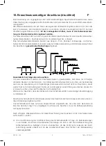
The storage tank is operated using the hot water valve of the service fitting (mixer tap). As a result, the
storage tank is constantly under line pressure. To protect the internal boiler from overpressure during
heating, the appearing expansion water is discharged through the safety valve.
In order to avoid damages to the hot water tank from overpressure, it is absolutely necessary to
replace any furred safety valves. The non-return valve prevents the hot water from flowing back into
the cold water supply net in the case of a loss of line pressure, thus protecting the boiler from heating
up without water. Using the shutoff valve, the storage tank can be separated in relation to water and
thus also from the cold water supply network, and emptied through the drain valve, if required.
11. Power Connection
E
11.1 General Information
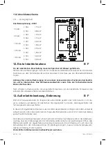
a) The electrical connection must principally be implemented in accordance with the circuit diagram
affixed inside the connecting area of the tank!
b) Observe the correct supply voltage!
c) An all-pole disconnecting switch with a contact gap width of 3 mm must be provided in the
power supply line. Automatic safety cut-outs are also permissible as disconnecting switch devi-
ces.
d) The connecting cable must be inserted into the connecting area of the tank through the screwed
cable connection and secured against pulling and twisting by means of the strain relief device.
For coil tanks, a second cable entry must be provided for the charge pump control cable.
e) The hot water tank must be isolated first from all possible sources of electrical power in accor-
dance with EN 50110 (ÖVE, TAEV) when being mounted and for interventions in the device. The
system must be protected against switching on again of the power supply prior to any additional
works (unscrew fuses, trigger line circuit breaker).
Summary of Contents for EHT Series
Page 39: ......


