AUSTRALIAN MONITOR AM1600 Operation Manual Download Page 16

6. Two Ohm or
Not Two Ohm

NOTE: Ensure adequate ventilation and monitor the
FAULT indicators to guard against thermal shutdown
when driving two ohm loads.

A preamble.

The load that a loudspeaker presents to an amplifier is
very complex and at different frequencies can be
inductive, capacitive, resistive, or a combination of
these (reactive). With the complex interaction of these
attributes, which alter from loudspeaker to loudspeaker,
a definitive load for an amplifier does not really exist.

Loudspeakers operating within an enclosure are
specified with a nominal impedance. This nominal
impedance is only a rough guide to the load it presents
to an amplifier.

As an example, a loudspeaker with a nominal impedance
of say 8 ohms, may have an impedance of over 50
ohms at resonance (bass frequencies), drop to less
than 6 ohms after the resonance peak (through its mid
band area) and then increase to over 16 ohms for higher
frequencies.
A 4 ohm load makes an amplifier work "harder" than an
8 ohm load at the same voltage, as double the current
is required.
Though various loudspeakers may be marked with the
same nominal impedance, some loads are more difficult
than others.
Bass frequencies usually exhibit higher impedances
and require higher voltages to achieve the desired
result. They also reflect higher energy back to the
amplifier simply due to the amount of cone excursion
involved at lower frequencies.
The  Mid frequency band usually offers the lowest
impedances and the highest duty cycles requiring both
high voltage and high current.
The High frequency region usually offers a moderate
impedance and usually does not need much voltage
but the instantaneous current demand can be much
greater than you think.
As well as this burden on the amplifier, the transient
waveforms found in actual use can demand a lot more
current than the "steady-state" sinewaves used in
most amplifier bench tests.

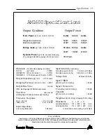
The power output of your 

AM1600

 amplifier quoted on

the specification sheet is derived from a voltage

excursion into a resistive load for a sine wave at a given
frequency. Though this method is in line with the
various standards that exist, it only gives an indication
to the maximum voltage swing (before clipping) for a
given load. This method of rating power does not give
an indication of the current (Ampere) capability of the
amplifier, nor does it show the amplifier’s ability to
sustain high energy waveforms.

Your 

AM1600

 amplifier has been specifically designed

to be able to deliver more than twice the current than
that shown on the specification sheet to cope with
difficult loads and/or high energy waveforms.

This extra current reserve is the result of over engineering
and is the headroom the amplifier utilizes to control the
loudspeaker and deal with the “reactive energy” from
the loudspeaker load that has to be dissipated within
the amplifier.

Your 

AM1600

 amplifier is able to drive 2 ohm loads or

operate in BRIDGE mode into 4 ohms. The operator
must be aware that when driving 2 ohm loads or bridged
4 ohm loads that the currents running in the output
stage are very large and will cause greater heat build
up within the amplifier than higher impedance loads.

The Front Panel FAULT Indicators can be used to
provide an indication of the "difficulty" of the load and
will give the operator an indication of the heat build up
in the output stage.

If the fault indicators flash with the "clip" LEDs or do not
illuminate until well into clipping then the load can be
considered as normal or easy.

If the fault indicator starts to flash before the "clip"
LEDs then the load should be considered complex
and/or difficult.

For the more complex and/or difficult loads, the
illumination of the "fault" LED on programme peaks
should be interpreted as the output level limit. Driving
the output continuously past this point could result in
muting of the output stage, breakers tripping or
premature thermal shutdown.

The fault detection circuit is also thermally
compensated, and fault indication will occur earlier
when the unit is hot. If the "fault" LED continually
lights earlier than normal, then the unit is heating
up. If the signal level is not reduced to compensate
for the heating of the unit then thermal shutdown
may occur.

16  Two Ohm or Not Two Ohm

Summary of Contents for AM1600

Page 1: ...O p e r a t i o n M a n u a l AM1600 ...

Page 2: ...n equilateral triangle is intended to alert the user that there is important operatingandmaintenanceliteraturethataccompanies the unit The unit should not be operated in a situation where it mayencountertheentryofwater rain oranyfluids To exposetheunittotheaboveconditionsmaymakethe operation of the unit hazardous and increase the risk of electrical shock The user should not attempt to service the ...

Page 3: ...witching control Input muting at turn on Inputovervoltageprotection Radio frequencyinterferencesuppression Short circuit protection and indication Active balanced inputs 21 Position detented attenuators Massive heat sink heat exchangers Efficient front to back cooling Quad twin speed axial fans Multi role level fault indication Front and rear carry handles Front and rear mounting points High quali...

Page 4: ... Operation 13 5 Bridge Mode 15 6 Two Ohm or Not Two Ohm 16 7 Maintenance 17 8 Warranty 18 9 Specification 19 List of Illustrations Page Figure 1 Block Diagram 5 Figure 2 Front Panel Layout 6 Figure 3 Rear Panel Layout 8 Figure 4 Case Dimensions 10 Figure 5 Speakon Connector Wiring 12 Figure 6 Bridge Mode Speaker Wiring 15 ...

Page 5: ...evity The AM1600 amplifiers are 3 unit 5 25 tall 19 wide rack mountable units Each channel of the amplifier comprises a balanced active input with an attenuator driving a differential class A drive stage which in turn drives a fan cooled class AB MOSFET output stage configured as a sourcefollower Theunitoperatesfromahighcurrent capable linear power supply Theseunitshavebeenspecificallydesignedtode...

Page 6: ...6 Controls Connectors Figure 2 Front Panel Layout 2 Controls Connectors Indicators Insert 1 VU Meter Satus Indicator ...

Page 7: ... LED will not illuminate during normal use of the amplifier In the advent of a thermal overload this LED will illuminateredindicatingthattheinternaloperating temperature of one or both amplifier channels has exceededasafelevelofoperationandthe amplifier willbeshutdown Thefanswillcontinuetorunand oncetheamplifierhascooleddownsufficiently the amplifierwillstartupautomaticallyprovidingInrush Current ...

Page 8: ...8 Controls Connectors Figure 3 Rear Panel Layout ...

Page 9: ...VE BLUE NEUTRAL GREENANDYELLOW EARTH Controls Connectors 9 CAUTION Your amplifier must always be earthed 9 Mains Circuit Breaker A push to reset thermal acting circuit breaker is suppliedonyouramplifierprovidingoverallprotection of your amplifier s power supply and the interconnectingmains Thebreakerwillisolatethe active mains conductor in the event of a high current internal fault or in continued...

Page 10: ...Figure 4 Dimensions 10 Installation ...

Page 11: ...This support can be provided by secure shelving support rails or a rearrackmountingstriptomatchupwiththerearrack mount points provided on your amplifier Cooling EachchannelofyourAM1600amplifieriscooledbyan axial fan which draws cool air from the front of the unit andexpelstheheatedairviatherearoftheunit These units offer two speed fans which run at half speed switching to full speed when the inter...

Page 12: ...ctlytothechassisoftheconnector Do not link this lug to pin 1 at the amplifier s input as it will defeat the amplifier s input grounding scheme This lug is often referred to as a drain and is used to provide a termination to the chassis for shielding purposes when a floating signal ground is required between the source and destination or when disconnecting the signal ground is required to reduce ea...

Page 13: ...mend turning the attenuators on your amplifier down when turning the unit on When you power up your amplifier your amplifier goes through an establishment period before it will acceptsignal TheInrushCurrentSuppression ICS circuit is in operation for the first 0 5 seconds This limitsthemainscurrenttoprevent nuisancetripping of circuit breakers During this period the THERMAL LED will flash red whils...

Page 14: ...d from a balanced signal source NOTE Be wary of quasi balanced outputs these are often no more than floating unbalancedoutputs 14 Operation 1 2 Each channel of your amplifier has a nominal balanced input impedance of 18k Ohms 1kHz and should not present a difficult load for any signal source Your signal source i e the equipment feeding the amplifier should have an output impedance of 600Ohmsorlowe...

Page 15: ...foranapplica ble load AsshowninFigure6 therearefourstepsinsettingup yourAM1600amplifierforrunningitinBRIDGEmode Whilst the amplifier is off 1 ConnectthesignalsourcetotheChannel Afemale inputXLR 2 Loop from Channel A male XLR to Channel B fe male input XLR with a Reverse Phase Lead A reverse Phase Lead is wired Channel A Channel B Pin 1 to Pin 1 Pin 2 to Pin 3 Pin 3 to Pin 2 3 Connect your load bet...

Page 16: ...eatagiven frequency Though this method is in line with the variousstandardsthatexist itonlygivesanindication to the maximum voltage swing before clipping for a given load This method of rating power does not give an indication of the current Ampere capability of the amplifier nor does it show the amplifier s ability to sustainhighenergywaveforms YourAM1600amplifierhasbeenspecificallydesigned to be...

Page 17: ...eed only hold the fan rotor still and wipe the dust off the blades Many users stall the fan and use Maintenance 17 compressed air to blow the dust off the fan blades It is important to note that the fan blades must be held still whilst blowing air over the blades otherwise you may burn out the bearings in the fan NOTE Make sure the unit is off and is unplugged from the mains Give the main filter c...

Page 18: ...ERIES2YEARWARRANTYREGISTRATION IMPORTANT Please complete this card and return it immediately after unpacking the product This card is to be sent DIRECTLY to Australian Monitor NOTE Warranty is effective ONLY upon receipt of this card COMPANY NAME MODEL ADDRESS SERIAL No DATE PURCHASED CITY DEALER STATE CODE COUNTRY Ensure that you fill out and send your warranty registration card Use this copy to ...

Page 19: ...ms THD N 1 kHz 0 005 IMDSMPTE 60 Hz 7 kHz 4 1 0 015 IMD DIM 30 3 15kHz square 15 kHz 0 007 Output Impedance 1 kHz 0 013 ohms Damping Factor 1 kHz re 8 ohms 650 1 Output Rise Time 2 2µS 80 leading edge of 20kHz square wave Slew Rate 65V per µS leading edge 20kHz square wave clipping Frequency Response 20 Hz 20 kHz 0 5 0 15 dB 3dB points 5 Hz 90 kHz Input Impedance Line to Line Balanced 18k ohms Inp...

Page 20: ...y Ph 02 9647 1411 Fax 02 9648 3698 E mail nsw audiotelex com au Melbourne Ph 03 9890 7477 Fax 03 9890 7977 E mail vic audiotelex com au Brisbane Ph 07 3852 1312 Fax 07 3252 1237 E mail qld audiotelex com au Adelaide Ph 08 8352 4444 Fax 08 8352 4488 E mail sa audiotelex com au Perth Ph 08 9228 4222 Fax 08 9228 4233 E mail wa audiotelex com au Auckland Ph 09 415 9426 Fax 09 415 9864 E mail audiotlx ...

Reviews: