background image


2. Product 


Caution 

It is important to familiarize yourself with the functions and operation of the product through the 
manual in order to use the device correctly. 

Incorrect handling can cause damage to the product or accidents. Please read this manual 
carefully before use.


2.1 

Model classification code


 ESS Series are classify as rated output. 

 
2.2 Product features 

• This is an energy storage system using a battery. It uses PV power and night electricity to charge the 
battery. 
• 

Utilizing the generated PV power to the maximum, the grid energy storage discharge is executed at the 

planned time and the output is single phase 2 wire system.


• 

Maximum power point tracking control is performed to maximize the power generated from the PV cell.


• 

You can set the optimal operating condition through the LCD key and check the operation status of the 

system conveniently.


• 

High efficiency and low distortion rate are achieved through optimal control and design using high 

performance semiconductor devices.


• 

It has UPS (Uninterruptible Power Supply) function that can supply emergency load power in case of power 

failure.


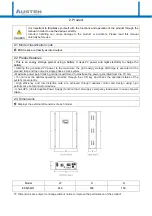
2.3 

Dimensions


Displays the external dimensions of each model.


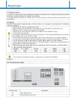
Model W  H  D 

ESS(3kW) 446 

630 

150 


Dimensions are subject to change without notice to improve the performance of the product.


Summary of Contents for ESS 3kW

Page 1: ...Document ESS Model000 20180514 INSTALLATION OPERATION MANUAL 3kW ...

Page 2: ...Installation and Wiring 3 1 Moving a product 3 2 Installation 3 3 Repair product 3 4 Wiring 3 5 Terminal block shape 4 Operation 4 1 KEYPAD 4 2 Functional group 4 3 Detail of function 4 4 System protection function 4 5 Basic operation and stop 5 Product Specification 5 1 Product specifications 6 Inspection and Caution 6 1 Inspection 6 2 Caution of usage 7 Quality Assurance ...

Page 3: ...Installation Manual Be sure to read this manual and other references thoroughly before installation ...

Page 4: ... electronic device Rain water dust and oil have to avoid during installation and operation Please avoid corrosive and flammable gas liquids metallic debris and flour are entering the electronic device Keep Store and Move it within the range of 10 C to 40 C in ambient temperature Do not touch the inside of the product within 15 minutes after turn off Wait for the internal capacitor to discharge com...

Page 5: ...rage discharge is executed at the planned time and the output is single phase 2 wire system Maximum power point tracking control is performed to maximize the power generated from the PV cell You can set the optimal operating condition through the LCD key and check the operation status of the system conveniently High efficiency and low distortion rate are achieved through optimal control and design...

Page 6: ...fied these conditions If the ambient temperature exceeds this range 10 C to 40 C due to the heat from operation cool it with a cooling equipment PCS dissipate heat from operation please secure enough space to prevent thermal saturation Humidity If humidity is high it may cause oxidation corrosion of the metal parts and insulation failure may occur Install in a place where the relative humidity is ...

Page 7: ...terminal Connect the earth terminal of the power terminal block to the earth pole Resistance must be less than 100 Ohm with a wire of 4mm3 or more Do not share the ground wire with the power unit It may cause electric shock and ground fault Connect the PV input power to the input terminals and of the product and turn on the power Connect the power supply of the system so that the phase rotation sh...

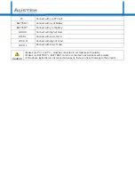
Page 8: ... L Connect with Low of Grid LOAD H Connect with High of Load LOAD L Connect with Low of Load Caution Make sure PV and PV must be connected in accordance with polarity Make sure BATTERY BATTERY must be connected in accordance with polarity If the above instruction is not connected properly there is a risk of damage to the product ...

Page 9: ...Operation Control Be sure to read this manual and other references thoroughly before installation ...

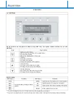
Page 10: ...data 3 Change the menu type and display 1 Down arrow key 2 Decrease the value when input a data 3 Change the menu type and display LED display LED Type Function LED Type Function 100 Current battery charge status SOC GRID Lights up when the system is in normal operation 80 PV Lights up when PV power is connected 60 INV Lights up when the inverter is operating in the system 40 FAULT When system fai...

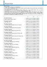
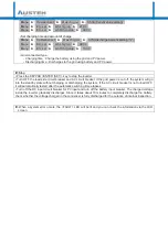
Page 11: ...line are as follows and displayed in real units A B C Screen Frame 1 Battery Voltage Power Current Screen Frame 2 Year Date Time Screen Frame 3 Cumulative power generation amount of inverter Screen Frame 4 Cumulative received power amount of inverter Screen Frame 5 Cumulative power supply amount of load side Screen Frame 6 Cumulative received power amount of Power Grid Screen Frame 7 Cumulative po...

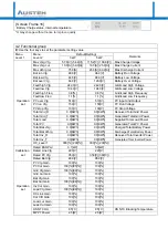
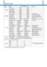
Page 12: ...tg 150 V 150 V PV Run Voltage PV stop Vtg 100 V 100 V PV Stop Voltage Total Grid_R 0 0 KWh 0 0 KWh Received Total Grid Power Total Grid_T 0 0 KWh 0 0 KWh Generated Total Grid Power Total Load 0 0 KWh 0 0 KWh Supplied Total Load Power Total PV 0 0 KWh 0 0 KWh Generated Total PV Power Total Bat chrg 0 0 KWh 0 0 KWh Charged Total Battery Power Total Bat dchrg 0 0 KWh 0 0 KWh Discharged Total Battery ...

Page 13: ...um Password Setting Line Trans Time 10 Sec 300 Sec 10 Sec 300 Sec Run Delay Time Self Off Time 20 Min 20 Min Automatic Stop Time Grid pwr lmt 2 0 Kw 2 0 Kw Grid Charging Power Setting SOC Low Lmt 20 20 Battery Protection Capacity Bat capacity 200 Ah 100 Ah 200 Ah 100 Ah Battery Capacity Sch chrg run 21 00 h m 21 00 h m Charge Start Time Sch chrg stop 06 00 h m 06 00 h m Charge Stop Time Sch Dchrg ...

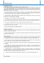
Page 14: ...y below the set DC over voltage Total PV power generation is cumulatively recorded Battery voltage control Battery is charging with the maximum charging current up to the maximum charging voltage with constant voltage constant current charging When the battery discharges to the minimum discharge voltage during discharging it stops ESS and generates low voltage signal Line monitoring Judgement abou...

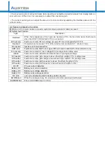
Page 15: ...verter Inverter overcurrent detection IGBT error Fault occurs when IGBT error signal of Drive board is detected for Driver fault cnt only PV over vtg Fault occurs when PV over voltage 510V is larger than setting value Island Fault occurs when anti island is detected due to grid system outage OV inverter Fault occurs when grid voltage is above Fault high volt Def 11 setting value UV inverter Fault ...

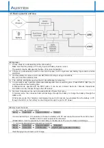
Page 16: ...al Operational information can be checked through the LCD screen 6 Normal Schedule can be set in Operation Mode of Select Set menu 1 Normal mode the connected load will discharge through the battery or charge the battery through the GRID or PV 2 Schedule mode the charging discharging time set in Etc set can be generated from the battery or PV through the GRID or the battery can be charged through ...

Page 17: ...oad side circuit breaker and AC circuit breaker If the grid power is cut off the system will go into the standby state without charging or discharging the system If the AC circuit breaker is not turned OFF it will automatically restart after the automatic switching time elapses Turn off the DC input circuit breaker for PV input and turn off the battery input breaker The charged voltage inside the ...

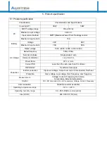
Page 18: ... Single phase 2 wire Harmonic distortion Less than 5 Power factor 95 or more Current THD Less than 3 each less than 5 of total TOPOLOGY Transformer less type Protection Inverter protection Input over voltage Output over current Overloaded Overheat Protection Over voltage Low voltage Over frequency Low frequency Measurement Voltage Current Frequency Run mode Temperature External temperature Control...

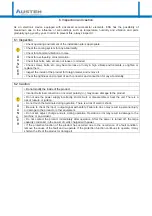
Page 19: ...lity 6 2 Caution D A N G E R Do not modify the inside of the product Incorrect terminal connection or incorrect polarity may cause damage to the product Do not wire the power supply incorrectly short circuit or disassemble or heat the unit There is a risk of rupture or ignition Do not touch the terminals during operation There is a risk of electric shock Be sure to check the input output signal wi...

Page 20: ...l not be subject to the warranty period and will be replaced and repaired for a fee 1 Damage caused by intention or negligence of the consumer 2 Failure caused by repair at a place other than our designated service center 3 Failure due to abnormal power supply or defective connection device 4 If the consumable part has reached its end of life and needs to be replaced 5 Failure or defect of product...

Reviews: