Aussie Pumps QP Installation, Operation And Maintenance Manual Download Page 3

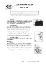
Australian Pump Industries 

Page 

3               document number: QPWP151204


DISASSEMBLY & ASSEMBLY 

For centrifugal transfer pumps 

Check Valve 


a.  Unscrew suction cover set bolt or screw, and remove the suction cover. 
b.  Unscrew the set bolt or screw with washer, and remove the check valve. 
c.  For setting the new check valve, screw the set bolt or screw to fit the valve 

with valve seat of suction cover. 

d.  Install the suction cover with O-ring or packing. 


a. Volute Casing 

a.  Unscrew the casing set bolt, and remove the casing from the casing cover. 
b.  Remove the volute casing that is placed into casing cover. 
c.  Install the new volute casing with O-ring or packing into the casing cover 

correct position. 

d. Adjust the clearance between front surface of impeller and side plate volute 

casing to be within 0.2 to 0.5mm (0.008 to 0.020 inch) when the volute casing 
is pushed in by adjusting the number of adjusting liners at impellerboss. 

e.  After confirming the volute casing to the casing cover, and screw the casing 

set bolts evenly and tightly. 


b. Impeller 

a.  Disclose the impeller by removing the volute casing same way as above. 
b.  Loosen the impeller by tapping gently with a mallet in a counter clockwise 

direction. 

c.  Turn impeller counter clockwise, and remove from shaft. 
d.  Remove the mechanical seal from the impeller, and set it at the back side of 

new impeller. 

e.  Screw the new impeller on engine shaft by turning in the clockwise direction, 

and make it tight by tapping gently with mallet in a clockwise direction. 

f.  Set the volute casing and casing as mentioned above 


c. Mechanical Seal 

a.  Remove the impeller as mentioned above 
b.  Replace with a new mechanical seal at the back side of removed impeller 

and at the seat of casing cover. 

c.  Check the scaling surfaces of mechanical seal free dust, and set the impeller, 

volute casing and casing as in the way abovementioned 3. 


For Trash Pumps 

Clogged Impeller 

a.  Unscrew drain set handles and dismantle the drain cover from casing. 
b. Dismantle volute casing. 
c.  Wash impeller with water. 
d.  Place volute casing O-ring and drain cover O-ring and screw drain cover after 

washing sealing surface with water. 

e.  Screw drain cover set handle evenly at right and left side. 

Summary of Contents for QP

Page 1: ...dy If a hose is used it should be of the reinforced type to prevent collapsing under vacuum All suction system pipe or hose and connections must be free of air leaks as even a very slight leak will greatly reduce pumping efficiency and priming ability The pump should be installed with the trash strainer on the suction line to prevent oversize solids from being drawn into the suction system Dischar...

Page 2: ...e are no suction line leaks B 5 Shutdown Operation is stopped by stopping the engine as outlined in the Engine Instruction Manual Always operate at no load for 2 or 3 minutes to allow cooling before shutdown When the pump has been operating in freezing weather or in pumping liquid containing considerable amounts of trash and or foreign matter it is advisable to remove both the drain plug and the p...

Page 3: ...et bolts evenly and tightly b Impeller a Disclose the impeller by removing the volute casing same way as above b Loosen the impeller by tapping gently with a mallet in a counter clockwise direction c Turn impeller counter clockwise and remove from shaft d Remove the mechanical seal from the impeller and set it at the back side of new impeller e Screw the new impeller on engine shaft by turning in ...

Page 4: ...ed with new rotary section spring Check to see if the mechanical seal O ring is placed correctly to the seat h Set new mechanical seal rotary section and spring with the sleeve to fit the slit of the sleeve with spring stopper i Screw the impeller as described above Troubleshooting PROBLEM CAUSE REMEDY Pump does not turn over Impeller jamming Adjust impeller spacing disassemble and clean Air leak ...

Page 5: ...L 1 USE COMMON SENSE Most accidents can be avoided by using common sense and concentrating on the job to be done 2 Do not wear loose clothing that can become entangled in operating machinery 3 Do not operate pump without guards in place 4 Do not pump hazardous material flammable caustic etc 5 Only qualified personnel should install and operate pump 6 Secure the pump after it is in its operating po...

Page 6: ...exhaust fumes when working in the area of the engine Exhaust gases are colourless odourless and deadly poison c Never operate near a building where exhaust gases can seep inside for example through an open window or a door d Never operate in a pit or sump without making provisions to suck the exhaust gases out 2 EXHAUST SYSTEM a Keep exhaust system components tight and in good working condition b ...

Page 7: ...T WATER FLOWING THROUGH IT Overheating pumps can cause severe burns and injury If overheating of pump casing occurs a Stop the pump immediately b Allow the pump to cool completely c Slowly and cautiously vent the pump C ELECTRIC MOTOR POWERED PUMPS 1 GROUND FAULT CIRCUIT INTERRUPTER Never operate a pump with a plug in type power cord without a ground fault circuit interrupter 2 WET HANDS Never han...

Page 8: ...ircuits are dead and locked out before doing any maintenance or repair work on the pump 8 MOTOR OVERLOAD Do not exceed the manufacturer s recommendation for maximum lift or discharge head as this could cause the motor to overheat Use appropriate circuit breaker for fuse 9 EXPLOSIVE ATMOSPHERE Unless the pump has been designed for it never use it in any kind of possible explosive atmosphere CAUTION...

Reviews: