background image

14 


3. Control panel and other functions.


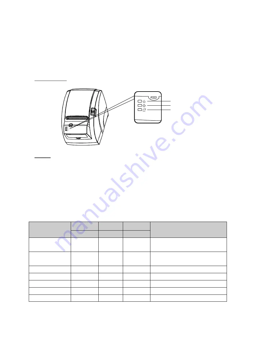
3-1. Control panel


You can control the basic paper feeding operations of  the printer with the button on the 

control panel. The indicator lights help you to monitor the printer’s status. 


Control Panel


Button


The button can be disabled by the ESC c 5 command. 


Press the FEED button once to advance paper one line. You can also hold down the FEED 
button to feed paper continuously. 


3-2. Error indicators


This section explains the different patterns signaled by the three LED indicators located on 

the top cover of the printer. 


STATUS 

PAPER 

ERROR  POWER 

REMARKS 

RED 

RED 

GREEN 

Power off 

OFF 

OFF 

OFF 

Normal power is not supplied to   

the printer 

Power on 

OFF 

OFF 

ON 

Normal power is supplied to the   

printer 

On line 

OFF 

OFF 

ON 

Normal error-free mode 

Cover open 

OFF 

ON 

ON 

Close cover 

Paper empty 

OFF 

ON 

ON 

Insert new paper roll 

Paper near end 

ON 

OFF 

ON 

Paper is low 

Test mode 

OFF 

OFF 

ON 

Ignored error led 


PAPER 

ERROR 

POWER 

Summary of Contents for ODP-200H-III

Page 1: ...3 Thermal Printer ODP 200H III All specifications are subject to change without notice...

Page 2: ...2 A software tool is available to configure the printer settings on AURES technical website www aures support fr...

Page 3: ...3...

Page 4: ...Control panel and other functions 14 3 1 Control panel 14 3 2 Error Indicator 14 4 Self Test 15 5 Hexadecimal Dump 16 6 Specifications 17 6 1 General Specifications 17 6 2 Auto Cutter Specifications 1...

Page 5: ...5 1 Parts Identifications...

Page 6: ...rinter 2 1 Unpacking Your printer box should include these items If any items are damaged or missing please contact your dealer for assistance The Printer User s Manual Roll Paper Adaptor Option Inter...

Page 7: ...f the cables make sure that both the printer and the computer are turned off INTERFACE CONNECTOR USB INTERFACE CONNECTOR PERIPHERAL DRIVE CONNECTOR POWER CONNECTOR For connection to a host computer Fo...

Page 8: ...put Printer transmit data line RS 232C level 3 RXD Input Printer receive data line RS 232C level 4 20 DTR Output Printer handshake to host line RS 232C level 6 DSR Input Data Send Ready 1 7 GND System...

Page 9: ...13 SELECT Output Printer status for ON OFF line 14 AUTO FEED Input Paper auto feed signal 15 GROUND System ground 16 GROUND System ground 17 NC 18 LOGIC H 3 3V 19 30 GROUND System ground 31 INIT Inpu...

Page 10: ...pplying a maximum current of 0 1A for 510ms or less when not printing PIN SIGNAL DESCRIPTION 1 Signal GND 2 Drawer kick out drive signal 1 Output 3 Drawer open close signal Input 4 24V 5 Drawer kick o...

Page 11: ...hat have the paper glued to the core because the printer cannot detect the paper end correctly Turn off power switch 1 Make sure that the printer is not receiving data Otherwise data may be lost 2 Ope...

Page 12: ...4 Insert new paper roll as shown 5 Be sure to note the correct direction that the paper comes off the roll 6 Pull out a small amount of paper as shown Then close the cover 7 Tear off the paper as sho...

Page 13: ...case repeat power on and off several times If the top cover is still stuck please follow the steps to release the papers from jamming 1 Make sure the printer is turned off 2 Take out cutter cover as s...

Page 14: ...e FEED button to feed paper continuously 3 2 Error indicators This section explains the different patterns signaled by the three LED indicators located on the top cover of the printer STATUS PAPER ERR...

Page 15: ...ding down the FEED button turn on the printer using the switch on the front of the printer to begin the self test The Self Test prints the printer settings and then prints the following Cuts the paper...

Page 16: ...down Feed button 3 Please press down Feed button more than 3 seconds after print out first page of self test 4 Now printer had entered into Hexa dump mode 5 Run any software program that sends data to...

Page 17: ...int speed 200mm sec 3 Dot density 180 DPI Hor Ver 180 180 0 142mm 0 142mm dot 4 Printing Width 180 DPI Max 72mm 512 dots 5 Number of print columns No of columns Font A Font B 180 DPI 42 56 6 Roll pape...

Page 18: ...18 8 Overall dimension...

Page 19: ...ckness is between 65 and100 m 6 3 Interface RS232C Serial Interface Centronics Parallel Interface IEEE1284 USB Interface Ethernet Interface 10Mbps 6 4 Electrical Characteristics 1 Input Voltage DC 24V...

Page 20: ...ng Temperature 5 C to 40 C Humidity 10 to 90 RH without condensation 2 Transport Storage except paper Temperature 20 C to 60 C Humidity 10 to 90 RH without condensation 6 6 Reliability 1 MCBF 60 milli...

Page 21: ...ers 15 ESC Set bit image mode 16 ESC Turn underline mode on off 17 ESC 2 Select default line spacing 18 ESC 3 Set line spacing 19 ESC Select peripheral device 20 ESC Cancel user defined characters 21...

Page 22: ...49 GS H Select printing position of HRI characters 50 GS I Transmit printer ID 51 GS L Set left margin 52 GS P Set horizontal and vertical motion units 53 GS V Select cut mode and cut paper 54 GS W S...

Page 23: ...23 8 FS C Select Kanji character code system 9 FS S 1 2 Set Kanji character spacing 10 FS W Turn quadruple size mode on off for Kanji character...

Page 24: ...Rev 1 0...

Reviews: