22
Assembly Instruction
FVM2
A
SSEMBLY
OF
A
PREPROGRAMMED
SET
Assembly locking drive FVM2
Mount the locking drive
FVM2
- as described below:
Determine fastenings.
Produce drill holes with appropriate cross-section.
For concealed mounting inside profi
les produce
the milling layouts. Please refer to the above-mentioned
hole layout drawings and mill layouts drawings
(see chapter „I
NSTALLATION
STEP
3“ or project-specifi c
documents and drawings).
Carefully clear away drilling swarfs to prevent
seals from being damaged.
Avoid surface scratches, for example by using
masking tape.
!
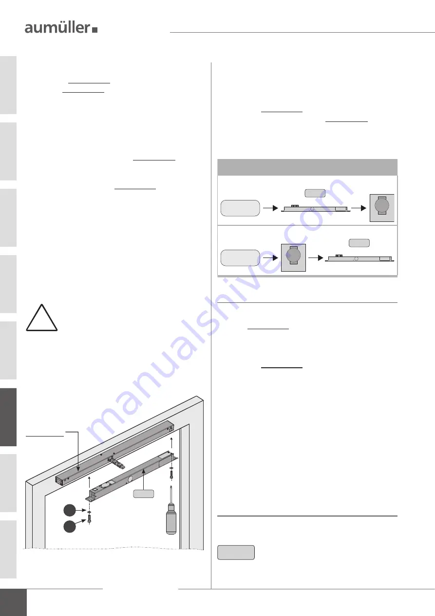
Mount the locking drive
FVM2
with screws
and
washers
in the pre-cut window frame.
Secure fasteners against loosening; i. e. by applying
removable thread-locking compound such as “Loctite”.
Switch on
the
control voltage
at locking drive
FVM2
and at the opening drive
-
in
CLOSE
direction.
First the opening drive moves in
CLOSE
direction, then
moves the locking drive
FVM2
.
Check whether the traverse path of the locking drive
FVM2
with the traverse path of the on-site locking bar
moves
synchronously.
If necessary, correct the locking stroke and the locking
position - with the
DIP
switches.
Move locking drive
FVM2
and opening drive in
OPEN
direction.
Switch off
the
control voltage
from the locking
drive
FVM2
and from the opening drive.
Sequence control:
24V DC
M
24V DC
M
Open
Locking drive
Opening
drive
Close
Locking drive
Opening
drive
FVM2
FVM2
opening drive
is unhinged
4
5
FVM2
RA
Test run: locking drive FVM2
Close the casement manually. During the test run
press the casement fi xed to the frame.
Switch on
the
control voltage
at locking drive
FVM2
and at the opening drive
-
in
CLOSE
direction.
Move locking drive
FVM2
and opening drive in
OPEN
direction.
Ensure the easy movement of the casement.
Open the casement manually.
Test run
Hinge opening drive on casement.
Make mechanical settings in accordance with „Assem-
bly and Commissioning Instructions“ of the drives.
Switch on
the
control voltage
at locking drive
FVM
and at the opening drive -
in
CLOSE
direction.
Check sequence control.
Ensure the easy movement of the casement.
N
OTE
When subsequent programming with
UniPC
the same assembly steps as
in the installation must be carri-
ed out with
preprogrammed set
(see separate: Installation Instructions for
UniPC).
06


