background image

5.

Repeat steps 1 and 2 for all further digits.

Having confirmed the last digit with 

Ok

, access to all parameters within one

user level is possible if the password entry is correct.

6.4.2.

Password change

Only the passwords of same or lower access level may be changed.

Example: If the user is signed in as 

Specialist (4)

, he/she can change passwords as

for password levels (1) through (4).

Device configuration M0053

Service functions M0222

Change passwords M0229

Menu item 

Service functions M0222

 is only visible, if user level 

Specialist (4)

 or higher

is selected.

Select main menu

1.

Set selector switch to position 0 (OFF).

2.

Press push button C

Setup

 and hold it down for approx. 3 seconds.

Display goes to main menu and indicates:

▶ Display...

Change passwords

3.

Select parameter 

Change passwords

 either:

click via the menu 

 to parameter, or

via direct display: press   and enter ID 

M0229

-

Display indicates:

▶ Change passwords

-

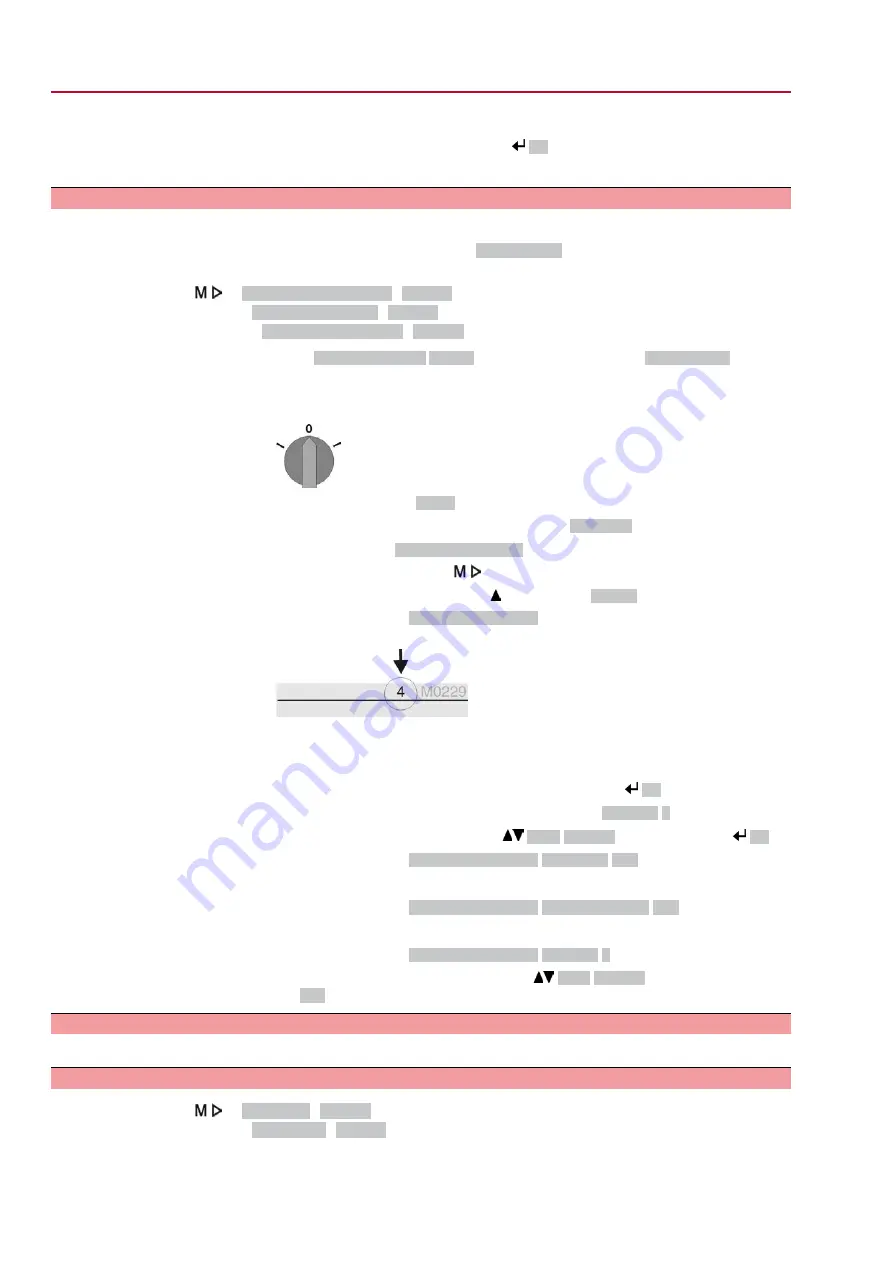
The user level is indicated in the top row (1 – 6), e.g.:

-

For user level 1 (view only), passwords cannot be changed. To change pass-
words, you must change to a higher user level. For this, enter a password via
a parameter.

4.

For a user level between 2 and 6: Press push button 

Ok

.

The display indicates the highest user level, e.g.:

For user 4

5.

Select user level via push buttons 

Up ▲ Down ▼

 and confirm with 

Ok

.

Display indicates:

▶ Change passwords Password 0***

6.

Enter current password (

 enter password).

Display indicates:

▶ Change passwords Password (new) 0***

7.

Enter new password (

 enter password).

Display indicates:

▶ Change passwords For user 4

 (example)

8.

Select next user level via push buttons 

Up ▲ Down ▼

 or cancel the process

via 

Esc

.

6.5.

Language in the display

The AUMATIC actuator controls display is multilingual.

6.5.1.

Language change

Display... M0009

Language M0049

38

 SQ 05.2 – SQ 14.2 / SQR 05.2 – SQR 14.2 Control unit - electromechanical

Operation

 AC 01.2 Intrusive Modbus RTU

Summary of Contents for AC 01.2

Page 1: ...et Modbus RTU Modbus TCP IP Foundation Fieldbus HART Part turn actuators SQ 05 2 SQ 14 2 SQR 05 2 SQR 14 2 Control unit electromechanical with actuator controls AC 01 2 Intrusive Assembly operation co...

Page 2: ...1 3 Applications in Ex zone 22 option 6 1 4 Warnings and notes 7 1 5 References and symbols 8 2 Identification 8 2 1 Name plate 11 2 2 Short description 12 3 Transport storage and packaging 12 3 1 Tra...

Page 3: ...NAMUR recommendation 46 7 3 Indication lights of local controls 47 7 4 Mechanical position indication via indicator mark 48 8 Signals output signals 48 8 1 Signals via fieldbus 48 8 2 Status signals...

Page 4: ...3 Fuses 70 11 3 1 Fuses within the actuator controls 70 11 3 2 Fuse replacement 70 11 3 2 1 Replace fuses F1 F2 71 11 3 2 2 Test replace fuses F3 F4 71 11 3 3 Motor protection thermal monitoring 73 12...

Page 5: ...danger to the application e g cause damage to the valve or the installation The manufacturer will not be held liable for any consequential damage Such risk lies entirely with the user Operation Prereq...

Page 6: ...or the determin ation of the maximum surface temperature The following conditions must be fulfilled to respect the maximum permissible surface temperatures at the actuator Respecting types of duty and...

Page 7: ...al personal injury hazard The signal word here DANGER indicates the level of hazard 1 5 References and symbols The following references and symbols are used in these instructions Information The term...

Page 8: ...e plate example manufacturer logo CE mark 1 Name of manufacturer 2 Address of manufacturer 3 Type designation 4 Order number 5 Actuator serial number 6 Operating time in s for a part turn movement of...

Page 9: ...ction 10 Control 11 Data Matrix code Motor name plate Figure 4 Motor name plate example manufacturer logo CE mark 1 Motor type 2 Motor article number 3 Serial number 4 Current type mains voltage 5 Rat...

Page 10: ...Positions 3 4 Year of manufacture 2016 16 Internal number for unambiguous product identification NS12345 Actuator terminal plan Position 9 after TPA Position transmitter version 0 Without position tra...

Page 11: ...are Operation setting and display can be either performed directly at actuator controls or alternatively from Remote via binary input signals or using another interface The following options are avail...

Page 12: ...ox using eyebolts and NOT to the actuator Actuators mounted to controls Attach ropes or hooks for the purpose of lifting by hoist only to the actuator and NOT to the controls Respect total weight of c...

Page 13: ...23 SQ 07 2 SQR 07 2 32 28 SQ 10 2 SQR 10 2 45 37 SQ 12 2 SQR 12 2 57 46 SQ 14 2 SQR 14 2 Indicated weight includes AUMA NORM part turn actuator with 1 phase AC motor electrical con nection in standar...

Page 14: ...ur products are protected by special packaging for transport when leaving the factory The packaging consists of environmentally friendly materials which can easily be separated and recycled We use the...

Page 15: ...heel 3 using the retaining ring 4 supplied Information The retaining ring 4 together with these operation instructions is stored in a weatherproof bag which is attached to the device prior to delivery...

Page 16: ...alve e g with bore and keyway two flat or square bore Information Assemble valve and part turn actuator in the same end position As standard the part turn actuator is supplied in end position CLOSED R...

Page 17: ...d screw with curved spring lock washer Figure 11 Mounting positions for coupling Table 7 Mounting position of the coupling within fitting dimensions according to AUMA definition SQ 14 2 SQ 12 2 SQ 10...

Page 18: ...up 7 2 If required shift part turn actuator by one tooth on the coupling 8 Fasten part turn actuator with screws Information We recommend applying liquid thread sealing material to the screws to avoi...

Page 19: ...us voltage Risk of electric shock Disconnect device from the mains before opening Electrostatic discharge ESD Risk of damage to electronic components Earth both operators and devices 1 Loosen screws a...

Page 20: ...Also refer to chapter Identification Name plate Figure 14 Motor name plate example 1 Type of current 2 Mains voltage 3 Mains frequency for 3 phase and 1 phase AC motors External supply of the electro...

Page 21: ...xt 230 V AC 115 V AC External power supply 1 A T 2 A T Fuse If actuator controls are mounted separately from actuator actuator controls on wall bracket Consider length and cross section of connecting...

Page 22: ...aid or shielding braid and shielding foil Screening Prior to installation please note Connect maximum 32 devices to one segment If more devices are to be connected Connect several segments using repea...

Page 23: ...plug socket connector and the socket carrier from terminal compartment Removing the cover is sufficient for connecting the fieldbus cables Technical data Table 15 Electrical connection via AUMA plug s...

Page 24: ...ins before opening 1 Loosen screws 2 and remove connection housing 1 2 Loosen screws 4 and remove socket carrier 5 from connection housing 1 3 Insert cable glands 8 suitable for connecting cables The...

Page 25: ...according to DIN 46228 6 Connect cables according to order related wiring diagram In case of a fault Hazardous voltage while protective earth conductor is NOT connected Risk of electric shock Connect...

Page 26: ...1 Insert the socket carrier 5 into the connection housing 1 and fasten with screws 4 2 Clean sealing faces of connection housing 1 and housing 3 Check whether O ring 3 is in good condition replace if...

Page 27: ...ltage Risk of electric shock Disconnect device from the mains before opening Electrostatic discharge ESD Risk of damage to electronic components Earth both operators and devices 1 Loosen screws 2 and...

Page 28: ...diagram S1 2 Termination switch for fieldbus termination Table 18 Functions of switches S1 and S2 1 2 Fieldbus termination channel 1 ON ON S1 Fieldbus termination channel 1 OFF OFF Fieldbus terminatio...

Page 29: ...ieldbus terminal compartment close Figure 23 Close fieldbus terminal compartment 1 Cover fieldbus terminal compartment 2 Screws for cover 3 O ring 4 Cable entries for fieldbus cables 5 Blanking plug 1...

Page 30: ...00 m If the actuator is equipped with a position transmitter RWG Connecting cables must be available as shielded version Versions with potentiometer in the actuator are not suitable We recommend AUMA...

Page 31: ...l connection 2 DS intermediate frame Application When removing the electrical connection or due to leaky cable glands there is a potential risk of ingress of dust and water into the housing This is pr...

Page 32: ...torques Tightening torques Terminal cross sections Conductor type 3 4 Nm 2 5 mm to 6 mm Solid wire and stranded 3 4 Nm 1 5 mm to 4 mm Fine stranded For fine stranded flexible wires connection is made...

Page 33: ...n direction CLOSE 6 1 2 Manual operation disengage Manual operation is automatically disengaged when motor is started again The handwheel does not rotate during motor operation 6 2 Motor operation Per...

Page 34: ...Run actuator in direction CLOSE Press push button 3 Information OPEN and CLOSE operation commands can be given either in push to run or in self retaining operation mode In self retaining mode the actu...

Page 35: ...selector switch 5 to position 0 OFF when navigating through the menu The bottom row of the display 6 serves as navigation support and explains which push buttons 1 4 are used for menu navigation Figu...

Page 36: ...ID Status menu and main menu are marked with an ID Figure 31 Marking with ID S ID starts with S status menu M ID starts with M main menu Group selection It is possible to select between status menu S...

Page 37: ...r level and permits different actions Table 21 User levels and authorisations Authorisation password Designation user level Verify settings No password required Observer 1 Change settings Default fact...

Page 38: ...via direct display press and enter ID M0229 Display indicates Change passwords The user level is indicated in the top row 1 6 e g For user level 1 view only passwords cannot be changed To change pass...

Page 39: ...user level via Up Down resulting in the following significations black triangle current setting white triangle selection not saved yet 8 Press Ok Display indicates Password 0 9 Enter password enter p...

Page 40: ...t Figure 36 Self test The language selection menu follows the startup menu Startup menu The current firmware version is displayed during the startup procedure Figure 37 Startup menu with firmware vers...

Page 41: ...in the navigation support 7 2 1 Feedback indications from actuator and valve Display indications depend on the actuator version Valve position S0001 This indication is only available if a position tra...

Page 42: ...commands S0003 The display S0003 indicates active operation commands like e g Operation in direction CLOSE or in direc tion OPEN the actual value E2 as bar graph indication and as value between 0 and...

Page 43: ...right stepping mode Table 22 Symbols along the pivot point axis Stepping mode Pivot point intermediate position with operation profile Symbol End of stepping mode Pivot point without reaction Start o...

Page 44: ...blinking exclamation mark after approx 3 seconds Figure 50 Fault For further information please also refer to Corrective action 7 2 3 Status indications according to NAMUR recommendation These indicat...

Page 45: ...NAMUR recommendation NE 107 If such an indication has occurred the display shows S0010 the number of indications occurred a blinking square with an oilcan after approx 3 seconds Figure 53 Maintenance...

Page 46: ...ications can be assigned to LEDs 1 5 Device configuration M0053 Local controls M0159 Indication light 1 left M0093 Indication light 2 M0094 Indication light 3 M0095 Indication light 4 M0096 Indicat li...

Page 47: ...dication Indicator disc rotates during actuator operation and continuously indicates the valve position For clockwise closing version the symbols rotate in counterclockwise direction for operation in...

Page 48: ...Signal DOUT 1 M0109 Default values Signal DOUT 1 Fault Signal DOUT 2 End position CLOSED Signal DOUT 3 End position OPEN Signal DOUT 4 Selector sw REMOTE Signal DOUT 5 Torque fault CLOSE Signal DOUT...

Page 49: ...ed Designation in the wiring diagram AOUT1 position For further information on this topic please refer to Manual Operation and setting 49 SQ 05 2 SQ 14 2 SQR 05 2 SQR 14 2 Control unit electromechanic...

Page 50: ...ping in end positions during standard operation End stop setting is generally performed by the valve manufacturer prior to installing the valve into the pipework Exposed rotating parts discs balls at...

Page 51: ...setting screw 4 clockwise results in a smaller swing angle Turning the setting screw 4 counterclockwise results in a larger swing angle 4 Turn setting screw 4 clockwise to the stop This completes the...

Page 52: ...g with the consent of the valve manufacturer Customer settings M0041 Type of seating M0012 End position CLOSED M0086 End position OPEN M0087 Default value Limit Setting values Limit Seating in end pos...

Page 53: ...e selection not saved yet 11 Confirm selection via Save The setting for the type of seating is complete 12 Back to step 4 CLOSED or OPEN Press Esc 9 3 Fieldbus address slave address baud rate parity a...

Page 54: ...Information The torque switches may also trip during manual operation Valve damage due to excessive tripping torque limit setting The tripping torque must suit the valve Only change the setting with...

Page 55: ...6 1 End position CLOSED black section set 1 Engage manual operation 2 Turn handwheel clockwise until valve is closed 3 Press down and turn setting spindle 1 with screw driver in direction of the arrow...

Page 56: ...n OPEN 5 Pointer Running direction OPEN 6 Mark Intermediate position OPEN is set 9 7 1 Running direction CLOSE black section set 1 Move valve in direction CLOSE to desired intermediate position 2 If y...

Page 57: ...tting spindle in the same direction and repeat setting process 9 8 Test run Only perform test run only once all settings previously described have been performed 9 8 1 Direction of rotation at mechani...

Page 58: ...ged to ensure that the position feedback 0 4 20 mA supplies correct values Operate actuator electrically via the push buttons OPEN and CLOSE of the local controls once to end position OPEN and once to...

Page 59: ...rk on the device 1 Clean sealing faces of housing and cover 2 Check whether O ring 3 is in good condition replace if damaged 3 Apply a thin film of non acidic grease e g petroleum jelly to the O ring...

Page 60: ...nt The switch compartment must be opened to perform any settings Refer to Switch compartment open All settings are made via the two push buttons S1 and S2 Figure 64 View on control unit when switch co...

Page 61: ...ng Refer to Faults during commissioning Set measuring range 2 Operate valve in one of the end positions OPEN CLOSED 3 Set desired output current 0 4 mA or 20 mA for 4 mA Hold down push button S1 for a...

Page 62: ...nds End position signalling is switched on or off Table 25 LED behaviour when end position signalling is switched on LED behaviour in end position Set output current LED is blinking slowly 4 mA LED is...

Page 63: ...rature impact 60 C to 80 C Ambient temperature2 5 k Transmitter potentiometer Power supply possible via AC AM actuator controls or external power supply 1 Depending on temperature range of the actuato...

Page 64: ...ed for 0 20 mA approx 0 1 mA for 4 20 mA approx 4 1 mA This ensures that the signal remains above the dead and live zero point 7 Move valve to end position OPEN 8 Set potentiometer 3 to end value 20 m...

Page 65: ...suring range 0 4 20 mA at EWG position transmitter cannot be set Check setting if required reset end positions Refer to Check switches and replace the switches if required Switch is defective or switc...

Page 66: ...aintenance S0010 Maintenance required For indicated value 0 Press push button Details to display a list of detailed indications For details refer to Faults and Failure table Collective signal 10 Indic...

Page 67: ...e started PVST abort Check movement at actuator Check parameter Reaction time M0634 No actuator reaction to operation commands within the set reaction time Wrn no reaction Check repair FO cables Optic...

Page 68: ...ng When connecting to a 3 ph or 1 ph AC system and with external 24 V DC supply of the elec tronics One of the phases L1 L2 or L3 is missing Phase fault Correct the sequence of the phase conductors L1...

Page 69: ...ent and the positioner is not active Wrong oper cmd Set selector switch to position REMOTE Selector switch is not in position REMOTE Sel sw not REMOTE Exit service software Operation via service inter...

Page 70: ...output power supply unit 115 V F4 Table 34 Secondary fuse F4 internal AC supply 1 AUMA art no F4 G fuse according to IEC 60127 2 III 5 x 20 mm Size K001 184 1 25 A T 250 V Voltage output power supply...

Page 71: ...ing Risk of functional failures Carefully assemble power supply unit to avoid pinching the cables 11 3 3 Motor protection thermal monitoring In order to protect against overheating and impermissibly h...

Page 72: ...atically reset or the fault signal has to be acknowledged The acknowledgement is made in selector switch position Local control LOCAL via push button RESET In selector switch position Remote control R...

Page 73: ...y When rarely operated Perform test run For enclosure protection IP68 After submersion Check actuator In case of ingress of water locate leaks and repair Dry device correctly and check for proper func...

Page 74: ...Observe the national regulations for waste disposal 74 SQ 05 2 SQ 14 2 SQR 05 2 SQR 14 2 Control unit electromechanical Servicing and maintenance AC 01 2 Intrusive Modbus RTU...

Page 75: ...ng procedure according to IEC 60034 6 Option Refer to motor name plate Permissible variation of mains voltage 10 Permissible variation of mains frequency 5 Mains voltage mains frequency Category III a...

Page 76: ...or actuators with 3 phase AC 1 phase AC DC motors or 380 400 V AC for actuators with 3 phase AC motors Options A resistance type heater of 5 W 24 V AC is installed in the actuator in combination with...

Page 77: ...10 6 starts Mechanical lifetime Silver plated contacts 24 V AC DC U min 250 V AC DC U max 20 mA I min 5 A at 250 V resistive load 3 A at 250 V inductive load cos phi 0 6 I max AC current 0 4 A at 250...

Page 78: ...he assignment of AUMA power classes please refer to Electrical data on actuator Via Modbus RTU interface Control and feedback signals 2 free analogue inputs 0 4 20 mA 4 free digital inputs Signal tran...

Page 79: ...trol inputs galvanically isolated from internal voltage supply Not possible in combination with PTC tripping device Option Redundant line topology with universal redundancy behaviour according to AUMA...

Page 80: ...r via fieldbus interface Reaction can be selected Stop run to end position CLOSED run to end position OPEN run to intermediate position Torque monitoring can be by passed during EMERGENCY operation Th...

Page 81: ...electronics against overvoltages on the fieldbus cables of up to 4 kV Overvoltage protection option AUMA plug socket connector with screw type connection Standard Electrical connection Gold plated co...

Page 82: ...LOSE Process representation output command signals End positions OPEN CLOSED Actual position value Actual torque value requires MWG in actuator Selector switch in position LOCAL REMOTE Running indicat...

Page 83: ...ndensation and high pollution Option Double layer powder coating Two component iron mica combination Coating AUMA silver grey similar to RAL 7037 Standard Colour Available colours on request Option Ac...

Page 84: ...14 Spare parts 14 1 Part turn actuators SQ 05 2 SQ 14 2 SQR 05 2 SQR 14 2 84 SQ 05 2 SQ 14 2 SQR 05 2 SQR 14 2 Control unit electromechanical Spare parts AC 01 2 Intrusive Modbus RTU...

Page 85: ...or limit torque 560 1 Sub assembly Output drive wheel for limit switching 023 0 Switch case for direction OPEN 560 2 1 Sub assembly Drive wheel for limit switching 024 0 Switch case for direction CLOS...

Page 86: ...14 2 AC 01 2 actuator controls with SD electrical connection 86 SQ 05 2 SQ 14 2 SQR 05 2 SQR 14 2 Control unit electromechanical Spare parts AC 01 2 Intrusive Modbus RTU...

Page 87: ...009 0 Sub assembly Relay board 011 1 Option board 012 0 Sub assembly Fieldbus connection board 050 1 Sub assembly Cover 500 0 Sub assembly Socket carrier complete with sockets 501 0 Sub assembly Pin c...

Page 88: ...without notice The latest versions are attached to the device upon delivery and also available for download at http www auma com 15 1 Declaration of Incorporation and EU Declaration of Conformity 88 S...

Page 89: ...89 SQ 05 2 SQ 14 2 SQR 05 2 SQR 14 2 Control unit electromechanical AC 01 2 Intrusive Modbus RTU...

Page 90: ...90 SQ 05 2 SQ 14 2 SQR 05 2 SQR 14 2 Control unit electromechanical AC 01 2 Intrusive Modbus RTU...

Page 91: ...posal 73 Double sealed 31 DUO limit switching 56 E Earth connection 32 Electrical connection 20 Electronic position transmitter 60 63 EMC 21 Enclosure protection 8 9 9 76 83 End position signalling 62...

Page 92: ...9 10 Out of specification indica tion on display 44 Output contacts 48 Output signals 48 Output signals Potential 21 Overvoltage category 78 P Packaging 14 Parity 53 Parking frame 31 Password 37 Pass...

Page 93: ...data 75 Technical data for switches 77 Temperature protection 9 Terminal plan 20 Test run 57 Torque indication on display 42 Torque range 8 Torque switching 54 Transport 12 Type device type 10 Type de...

Page 94: ...el 36 93 324 666 auma fabo hu www fabo hu Falkinn HF IS 108 Reykjavik Tel 00354 540 7000 os falkinn is www falkinn is AUMA ITALIANA S r l a socio unico IT 20023 Cerro Maggiore MI Tel 39 0331 51351 inf...

Page 95: ...ran 982144545654 info itg co ir Trans Jordan Electro Mechanical Supplies JO 11133 Amman Tel 962 6 5332020 Info transjordan net AUMA JAPAN Co Ltd JP 211 0016 Kawasaki shi Kanagawa Tel 81 0 44 863 8371...

Page 96: ...er GmbH Co KG P O Box 1362 DE 79373 Muellheim Tel 49 7631 809 0 Fax 49 7631 809 1250 info auma com www auma com Y005 958 003 en 1 18 For detailed information on AUMA products refer to the Internet www...

Reviews: