background image

WASTEWATER TREATMENT 

PLANT MODEL AT6 - AT50

15

• REMOVAL OF EXCESS SLUDGE

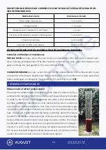
Maintenance mode

Maintenance intervals

Check sludge concentration

1 x 6 months

Sludge removal

1-2 x years

Replacement of membrane in the blower

1 x year

Check the airlift operation, aeration, flow regulator

1 x 6 months

Check the solids bag 

1 x 6 months

Clean the air filter in the blower

1 x 6 months

INSPECTION AND SERVICE ARE CARRIED OUT ONLY BY AUGUST SPECIALISTS OR AUTHOR

-

ISED REPRESENTATIVES:

All tasks performed must be recorded in the Unit maintenance documents.

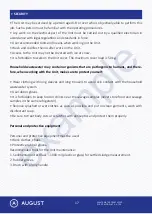
Measurement of settled sludge content

The amount of settled sludge or the settling of the mixture is determined by a 
sedimentation test flask (1000 ml) or a transparent vessel allowing the sludge 
to settle for 30 minutes. If the sludge does not settle in the sedimentation 
test flask, contact the Manufacturer or its representative who is authorised 
to perform the maintenance of the Unit. Take 1 litre of the activated sludge 
mixture from the aerated chamber and transfer to the sedimentation test 
flask. The sample is collected with the blower operating. Allow the mixture 
to settle for 30 minutes. After this period, check the amount of settled sludge 
(a clear difference between water and sludge should be visible). This should 
be 300-600 ml of sludge/1 l of water (most optimal: 400-500 ml of sludge/1 l 
of water). In such a ratio, the Unit achieves the highest treatment efficiency. 
The amount of settled sludge should be measured every six months, and the 

results should be recorded in the Unit maintenance register.

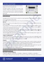
Controller notifications of maintenance

REPLACE FILTER

 warning – warns the user to clean or replace filter after half a year of blower oper

-

ation. Cleaning or replacement of the filter must be confirmed on screen: press the Δ button and Δ 
again to change the message NO to YES, and confirm with SET.

CHANGE MEMBRANE

 warning – warns the user for the replacement of the membrane after 1 year 

of operation of the blower. Replacement of the membrane must be confirmed on screen: press the Δ 
button and Δ again to change the message NO to YES, and confirm with 

SET.

example

Summary of Contents for AT-10

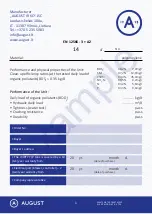
Page 1: ...WASTEWATER TREATMENT PLANT MODEL AT6 AT50 WASTEWATER TREATMENT PLANT TECHNICAL PASS AT SYSTEM SOLUTIONS FOR HUMAN AND NATURE e x a m p l e ...

Page 2: ... BDS5 0 35 kg d BDS5 SM ChDS NH4 N N 98 2 7 0mg l 97 2 12 0mg l 94 4 45 0mg l 99 5 0 2mg l 93 2 5 6mg l 93 3 0 6mg l Performance of the Unit Daily load of organic pollutants BOD5 Hydraulic daily load Tightness water test Crushing resistance Durability kg d m3 d pass pass pass Buyer s address The WWTP P P tank is covered by a 10 ten year warranty from Electrical part blower controller 2 two year wa...

Page 3: ... TECHNICAL DATA OF THE UNIT TREATMENT PROCESS MECHANICAL AND ELECTRICAL DEVICES AUGUST BASIC CONTROLLER CONTROL AND MAINTENANCE MANUAL REMOVAL OF SURPLUS SLUDGE UNIT MAINTENANCE MANUAL CERTIFICATE DECLARATION OF PERFORMANCE COMMENTS AND NOTES 1 3 4 7 8 9 9 11 13 15 16 19 20 21 2 WASTEWATER TREATMENT PLANT MODEL AT6 AT50 e x a m p l e ...

Page 4: ...ontaminants in the wastewater thus purifying the water In addition to food vital bacterial activity also requires oxygen therefore a blower comprising an integral part of the Unit is installed next to the Unit housing All household chemicals detergents cleaning agents etc if used moderately are allowed and do not cause harmful effects on the Unit In order to avoid operational problems it should be...

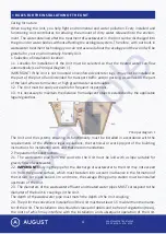
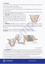
Page 5: ...essary to maintain the distance from adjacent objects established by the applicable legal regulations The Unit and the systems ensuring its functionality must be installed in accordance with the requirements of the effective legal regulations the technical or work project of the building instructions for installation work and these recommendations 2 Preparation for construction 2 1 The wastewater ...

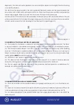
Page 6: ...he Units It is necessary to raise about 0 30 m of undisturbed soil to the groundwater level 3 6 The Unit is lowered into the pit using typical lifting mechanisms 3 7 After lowering the Unit into the pit and checking the design position depth horizontal vertical 3 2 IMPORTANT Pit depth depends on the depth of the wastewater pipe at the installation location The pit must have a funnel shape the diam...

Page 7: ... The indoor mounted blower must not come into contact with the wall or any other building structure If the blower is installed outdoors it must be protected against moisture rain and dust A blower container should not be installed in a place where water can run on it and accumulate High quality gaskets MUST be used in openings 4 2 220V 3X1 5 mm electric cable is connected to the Unit 4 3 The dista...

Page 8: ...tions of the Unit prepared by the Manufac turer which in each case is handed over to the Buyer together with the Unit and 4 4 The installation work of the Unit has been carried out by the Manufacturer or its authorised person or by a contractor having the necessary qualifications and the right to perform work for the construction of engineering networks or by the builder under the supervision of a...

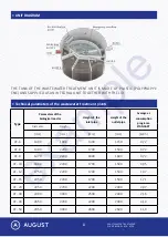
Page 9: ...he biological reactor Height of the inlet pipe Height of the outlet pipe Average el consumption programa STANDART Diameter Heigh mm mm mm mm kWh AT 6 1400 1800 1300 1150 0 72 AT 8 1400 2200 1700 1500 0 72 AT 9 1470 2200 1800 1600 0 72 AT 10 1600 2200 1700 1500 0 95 AT 12 1750 2200 1700 1500 1 37 AT 15 2050 2200 1700 1500 1 71 AT 20 2050 2700 2200 2000 2 07 AT 30 2300 3000 2500 2300 2 16 AT 40 2850...

Page 10: ...ids bag and must be removed later The solids bag is lifted by pulling the handle and cleaned Air distribution panel and adjustment valves A valve Controls air volume to airlift 1 internal recirculation Large bubbles mix the contents of section 1a whirling should be visible on the water surface The valve is partially opened B valve Controls air flow to the current regulator 3 Normally it is set to ...

Page 11: ...l production control If necessary you can set new settings but first you have to close all the valves and then follow the instructions above Flow controller The flow controller ensures flow balancing under high instantaneous loads bath wash basin etc The discharge of water from the biological wastewater treatment plant through the calibrated hole in the flow regulator is 3 l min 180 l h Blower The...

Page 12: ...enu is OPERATING MODE SELECT By a next pressing SET we enter into the selection of programs there we can move with Δ If we want to select a program select by Δ and then confirm it with SET Programs The microprocessor control unit AUGUST has the pre set standard mode in which it is ready to control the operation of the plant without other settings The display shows date and time and program STANDAR...

Page 13: ...g from the holiday it is enough to click Δ and the microprocessor switches automatically to the pre set standard program program WEEKEND HOUSE this was designed for treatment of waste water from weekend houses with occupation on weekends or once in a month Before leaving such an object program WEEKEND HOUSE is set After returning it is enough to click Δ and the microprocessor returns automatically...

Page 14: ...tion of the blower OPERATION AND MAINTENANCE INSTRUCTIONS Launching the Unit Setting the BASIC controller Connecting the blower Adjusting the air distribution manifold valves Filling activated sludge 0 25 m3 4 m3 depending on sewage treatment plant model and sludge concentration Unit shutdown The Unit is turned off upon disconnecting the controller Make sure to pump out the contents of the Unit wa...

Page 15: ...ges There are two types of alarm in the controller acoustic and optical The optical alarm system operates continuously The audible alarm will be triggered if the blower or controller is malfunc tioning or in case of power failure The audible alarm can be interrupted by pressing Δ Optical alarm Constant green blower operation is temporarily paused this is not a malfunction Flashing green blower ope...

Page 16: ...d sludge mixture from the aerated chamber and transfer to the sedimentation test flask The sample is collected with the blower operating Allow the mixture to settle for 30 minutes After this period check the amount of settled sludge a clear difference between water and sludge should be visible This should be 300 600 ml of sludge 1 l of water most optimal 400 500 ml of sludge 1 l of water In such a...

Page 17: ... evenly maintaining the water level difference between the chambers up to 15 cm The sludge concentration in the biological reactor of the Unit after removal must not be less than 300 ml l The pump pipe for pumping excess sludge must be placed carefully into the biological reactor of the Unit without damaging the aeration elements or other internal equipment The maintenance manual is part of the te...

Page 18: ...t are pathogenic to humans and there fore when working with the Unit make sure to protect yourself Wear clothing with long sleeves and long trousers to avoid skin contact with the household wastewater system Use rubber gloves It is forbidden to keep food or drinks near the sewage samples never store food and sewage samples in the same refrigerator Remove splashed or wet clothes as soon as possible...

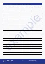
Page 19: ...WASTEWATER TREATMENT PLANT MODEL AT6 AT50 18 MAINTENANCE MANUAL OF WASTEWATER TREATMENT UNIT Date Visual inspection Completed tasks Sludge concentration ml l e x a m p l e ...

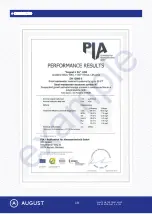
Page 20: ...WASTEWATER TREATMENT PLANT MODEL AT6 AT50 19 CERTIFICATE e x a m p l e ...

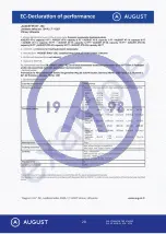
Page 21: ...WASTEWATER TREATMENT PLANT MODEL AT6 AT50 20 e x a m p l e ...

Page 22: ...WASTEWATER TREATMENT PLANT MODEL AT6 AT50 21 COMMENTS AND NOTES e x a m p l e ...

Page 23: ...WASTEWATER TREATMENT PLANT MODEL AT6 AT50 22 COMMENTS AND NOTES e x a m p l e ...

Page 24: ... AUGUST IR KO JSC Juodasis kelias 104a LT 11307 Vilnius Lietuva 370 5 235 5083 info august lt www august lt e x a m p l e ...

Reviews: