34
3.4 Power supply and connections for the electrical post heating coil KWout (option)
All the internal cables of the KWout coil to the main switch are factory wired. All that needs to be wired is the main
power supply to the main switch.
Wiring specifications:
Unit type
Supply voltage
KWout heating
capacity
Maximum
amps
HRglobal 800
HRglobal 800 ECO
3 x 400V + N
3 kW
4,3 A
HRglobal 1200
HRglobal 1200 ECO
3 x 400V + N
4,5 kW
6,5 A
HRglobal 2000
HRglobal 2000 ECO
3 x 400V + N
6 kW
8,7 A
HRglobal 3000
HRglobal 3000 ECO
3 x 400V + N
9 kW
13,0 A
HRglobal 4000
HRglobal 4000 ECO
3 x 400V + N
12 kW
17,3 A
HRglobal 5000
HRglobal 5000 ECO
3 x 400V + N
18 kW
26,0 A
HRglobal 6000
HRglobal 6000 ECO
3 x 400V + N
18 kW
26,0 A
3.5 Connecting the post heating water coil (option)
The post-heating water coil is delivered with a motorized 3-way valve (non-mounted).
3.5.1 Power supply:
Refer to installation and setup of post heating control manual (delivered with NV option).
3.5.2 Water connection (to be made by the installer):
•
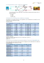
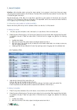
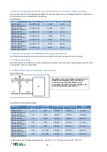
Connection schematic:
•
These are the specifications for the water coil connection:
Unit type
Diameter
on the coil
Diameter on
the valve
Coil Capacity (*)
Water flow (*)
Pressure loss (*)
HRglobal 800
HRglobal 800 ECO
1/2’’
G 1B
4,5 kW
199 l/h
1,4 kPa
HRglobal 1200
HRglobal 1200 ECO
1/2’’
G 1B
8,0 kW
353 l/h
6,5 kPa
HRglobal 2000
HRglobal 2000 ECO
1/2’’
G 1B
13,2 kW
585 l/h
20,4 kPa
HRglobal 3000
HRglobal 3000 ECO
1/2’’
G 1B
19,4 kW
857 l/h
11,1 kPa
HRglobal 4000
HRglobal 4000 ECO
1/2’’
G 1B
27,8 kW
1200 l/h
26,8 kPa
HRglobal 5000
HRglobal 5000 ECO
1/2’’
G 1 1/4B
37,5 kW
1657 l/h
56,9 kPa
HRglobal 6000
HRglobal 6000 ECO
1/2’’
G 1 1/4B
41,6 kW
1835 l/h
68,5 kPa
(*) Nominal values for following selection conditions: air in T°: 18°C, water in/out T: 90/70°C. For other conditions
refer to the HRglobal selection software or provided data sheet for the project.

