RMT 4161
1
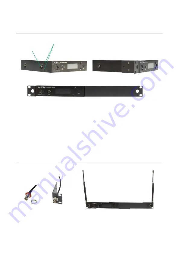
The holes for attaching rackmounts are located on the sides of the receiver.
2
The rackmounts are attached with two Phillips head screws and are intended to lay
over the Torx machine screw that holds the receiver enclosure together. For additional
support, the Torx screw may be removed and used as one of the fastening screws for
the rackmount.
3
After both metal pieces are fastened to the receiver, it is ready to be mounted into
the rack.
RMT 41 KIT
1
This kit includes the BNC cables needed for front mounting the antennas. Remove the
hex nut from the threaded end of the BNC connector.
2
Note: The rackmount has a hole that is slotted on one side. The flat portion of the BNC
connector must line up with the slotted portion of the hole in order to be pushed
through. It can only go in one way. Once it is through the hole, screw the nut back into
place and tighten.
3
After both sides are secure, connect the cables to Antenna A and Antenna B on the
back of the receiver. The antennas may now be front mounted to the BNC connectors.
RACKMOUNT INSTALLATION
1
1
2
2
3
3
Holes for rackmount screws
Machine screw
23


