OWNER’S MANUAL
AV 5.1k
/
12
AUTOMATIC
ON / OFF
HI
BAND
LO
LNS= Line Noise Suppressor
7.1
INPUT CONTROLS
7
Page 1: ...Release 1 1 www audison eu AV 5 1k OWNER S MANUAL CAR AUDIO MULTICHANNEL AMPLIFIER ...
Page 2: ... 2 1 A Channels 16 8 2 2 B Channels 16 8 2 3 C Channels 17 8 3 Example Front Rear Sub with IN A IN B IN C inputs 18 8 4 Example Front Rear Sub with IN A and IN B inputs 19 8 5 Example Woofer Mid HI Sub with IN A inputs 20 8 6 Example Woofer Tweeter Sub with SPK IN A inputs 21 9 ACCESSORIES AV bit IN 22 9 1 How to insert AV bit IN 23 9 2 Front panel 24 9 3 Control panel display 25 9 4 How to connec...
Page 3: ...ds control of cone and diaphragm resonance for speakers To achieve these goals it was necessary to develop new circuit solutions increase heat capacity design new moulds for baskets and diaphragms and define new assembly procedures and quality control A delicate balance of analysis and refinement led us to results exceeding our expectations and set a new benchmark for the category THE AV 5 1k AMPL...
Page 4: ...tracks nr 1 100A AFS spare fuse N 1 Allen wrench 0 118 nr 4 3 9 x 25mm 0 15 x 0 99 self tapping cross headed fixing screws 2 VCRA SUB volume remote control AV bit IN AV amplifiers digital interface TEST SIGNAL Track_01 sine sweep 10 min Track_02 white noise 15 min Track_03 pink noise 10 min Track_04 sine wave 50 Hz 0 dB 2 min Track_05 sine wave 1 kHz 0 dB 2 min CD ROM Owner s Manuals Manuali d uso...
Page 5: ...uctions in this manual carefully In order to design and create top level car hi fi systems you need to understand automobile mechanical and electrical issues very well if you think you lack the required knowledge or the proper tools please consult with a specialized installer A professional installation will ensure your system delivers all the performance you have paid for without affecting the sa...
Page 6: ...ary checking with a tester that there is continuity between the battery negative terminal and the fixing point If possible connect all components to the same ground point this solution rejects most noise Route all signal cables away from power cables Never run cables outside the vehicle you would not be protected against wear and in case of accidents When installing speakers and the cables that co...
Page 7: ...L AV 5 1k 7 5 INSTALLATION External size How to remove the panel Mounting size How to mount self tapping screw 3 9 x 25 mm 0 15 x 0 99 5 470 mm 18 50 220 mm 8 66 58 mm 2 28 399 mm 15 72 198 mm 7 8 Allen wrench 0 118 ...
Page 8: ...egative pole 4 CAP Terminal for connecting the positive pole of an external super capacitor 5 Left A Speaker Out 6 Right A Speaker Out 7 Left B Speaker Out 8 Right B Speaker Out 9 SUB OUT Speaker 10 Remote Sub Control inputs for remote control of the VCRA Sub volume control optional 11 Remote IN OUT REMOTE IN terminal for the remote cable coming from the device which turns on the amplifier REMOTE ...
Page 9: ...E FUSE 6 3 HOW TO CONNECT THE REMOTE SWITCH 6 AV 5 1k BL AL AR BR C SUB BATT GND CAP SUB VOL CONTROL REMOTE OUT IN 100A ASF Fuse provided AV 5 1k REMOTE OUT IN BL AL AR BR C SUB BATT GND CAP SUB VOL CONTROL REMOTE OUT to other amplifier REMOTE OUT ...
Page 10: ...O CONNECT THE SUB REMOTE VOLUME CONTROL 6 AV 5 1k REMOTE OUT IN BL AL AR BR C SUB BATT GND CAP SUB VOL CONTROL VCRA Sub remote control SPK IN 1 2 20V L R CH A L R CH B L R CH C IN B PR EO UT IN A 3CH IN B AR T IN A IN C L L R ON OF F PR EO UT ON ON OF F R IN A B IN C SUB FRONT REAR ART ON OFF REMOTE OUT IN SUB VOL BR CAP REMOTE OUT to other amplifier ...
Page 11: ...l left and right analog inputs 5 SPK IN CH B Channel B high level left and right analog inputs 6 SPK IN CH C Channel C high level left and right analog inputs 7 ART ON OFF Select ON to turn on the amplifier through the speaker power cable if the source does not feature a 12V DC REMOTE OUT Select OFF if REMOTE OUT from the source is available 8 IN B PREOUT ON Set the switch to ON to drive channel B...
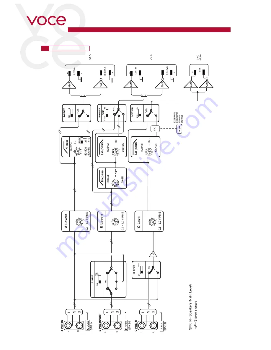
Page 12: ...OWNER S MANUAL AV 5 1k 12 AUTOMATIC ON OFF HI BAND LO HI LNS Line Noise Suppressor 7 1 INPUT CONTROLS 7 ...
Page 13: ... L R CH C IN B PREOUT IN A 3CH IN B ART IN A IN C L L R ON OFF PR EO UT ON ON OFF R IN A B IN C SUB FRONT REAR ART ON OFF SPK IN 1 2 20V L R CH A L R CH B L R CH C IN B PR EO UT IN A 3CH IN B AR T IN A IN C L L R ON OF F PR EO UT ON ON OF F R IN A B IN C FRONT REAR SUB SWITCH ON enables turning the product on from the SPEAKER IN CH A inputs OEM SOURCE OEM SOURCE 7 ...
Page 14: ...rtion 4 PASS MODE HI FULL Switch to select channel A filter type Select FULL to get a full range output signal Select HI to get an output signal to drive a MIDRANGE TWEETER In this case the output cut off frequency should be set by adjusting the HI PASS knob see section 5 5 HI PASS XOVER 50 Hz 500 Hz Adjustment of the channel A high pass filter cut off frequency By turning the knob it is possible ...
Page 15: ...Turn the amplifier off and check speakers and wiring 15 SPEAKER The yellow LED indicates a fault in the speaker connection It turns on when a speaker terminal short circuits with the vehicle chassis If when listening to music the sound stops for a while check if the yellow LED flashes it means there was a short circuit between a speaker terminal and the vehicle chassis Turn the amplifier off and c...
Page 16: ... 300 HI PASS CH A HI FULL x10 x1 50 130 80 1k HZ 250 400 HI PASS 250 650 300 5k HZ 1k2 2k3 LO PASS CH B HI FULL BAND 50 130 80 1k HZ 250 400 HI PASS 250 650 300 5k HZ 1k2 2k3 LO PASS CH B HI FULL BAND 50 130 80 1k HZ 250 400 HI PASS 250 650 300 5k HZ 1k2 2k3 LO PASS CH B HI FULL BAND 50 85 60 150 HZ 115 135 LO PASS CH C LO FULL 50 85 60 150 HZ 115 135 LO PASS CH C LO FULL 50 100 60 500 HZ 200 300 ...
Page 17: ... HZ 115 135 LO PASS CH C LO FULL 50 130 80 1k HZ 250 400 HI PASS 250 650 300 5k HZ 1k2 2k3 LO PASS CH B HI FULL BAND 50 130 80 1k HZ 250 400 HI PASS 250 650 300 5k HZ 1k2 2k3 LO PASS CH B HI FULL BAND 50 130 80 1k HZ 250 400 HI PASS 250 650 300 5k HZ 1k2 2k3 LO PASS CH B HI FULL BAND 50 85 60 150 HZ 115 135 LO PASS CH C LO FULL 50 85 60 150 HZ 115 135 LO PASS CH C LO FULL 50 130 80 1k HZ 250 400 H...
Page 18: ... PREOUT ON ON OFF R IN A B IN C 50 100 60 500 HZ 200 300 HI PASS 50 130 80 1k HZ 250 400 HI PASS 250 650 300 5k HZ 1k2 2k3 LO PASS 50 85 60 150 HZ 115 135 LO PASS CH A CH B CH C HI FULL HI FULL BAND LO FULL x10 x1 LEVELS 0 3 5V CH A ON TH OVL SPK AV 5 1k 1 5 2 3 4 CH B 1 5 2 3 4 CH C 1 5 2 3 4 AV 5 1k REMOTE OUT IN BL AL AR BR C SUB BATT GND CAP SUB VOL CONTROL L R SOURCE Front PREOUT Sub PREOUT R...
Page 19: ...REOUT IN A 3CH IN B ART IN A IN C L L R ON OFF PREOUT ON ON OFF R IN A B IN C 50 100 60 500 HZ 200 300 HI PASS 50 130 80 1k HZ 250 400 HI PASS 250 650 300 5k HZ 1k2 2k3 LO PASS 50 85 60 150 HZ 115 135 LO PASS CH A CH B CH C HI FULL HI FULL BAND LO FULL x10 x1 LEVELS 0 3 5V CH A ON TH OVL SPK AV 5 1k 1 5 2 3 4 CH B 1 5 2 3 4 CH C 1 5 2 3 4 AV 5 1k REMOTE OUT IN BL AL AR BR C SUB BATT GND CAP SUB VO...
Page 20: ...IN A IN C L L R ON OFF PREOUT ON ON OFF R IN A B IN C 50 100 60 500 HZ 200 300 HI PASS 50 130 80 1k HZ 250 400 HI PASS 250 650 300 5k HZ 1k2 2k3 LO PASS 50 85 60 150 HZ 115 135 LO PASS CH A CH B CH C HI FULL HI FULL BAND LO FULL x10 x1 LEVELS 0 3 5V CH A ON TH OVL SPK AV 5 1k 1 5 2 3 4 CH B 1 5 2 3 4 CH C 1 5 2 3 4 AV 5 1k REMOTE OUT IN BL AL AR BR C SUB BATT GND CAP SUB VOL CONTROL SUBWOOFER 2Ω S...
Page 21: ... OFF PREOUT ON ON OFF R IN A B IN C 50 100 60 500 HZ 200 300 HI PASS 50 130 80 1k HZ 250 400 HI PASS 250 650 300 5k HZ 1k2 2k3 LO PASS 50 85 60 150 HZ 115 135 LO PASS CH A CH B CH C HI FULL HI FULL BAND LO FULL x10 x1 LEVELS 0 3 5V CH A ON TH OVL SPK AV 5 1k 1 5 2 3 4 CH B 1 5 2 3 4 CH C 1 5 2 3 4 AV 5 1k REMOTE OUT IN BL AL AR BR C SUB BATT GND CAP SUB VOL CONTROL SOURCE PRE OUT to other amplifie...
Page 22: ... immediately amplified protecting it from deterioration over long distances The result is high quality music not reachable with any other analog system AV bit IN ASC is the management interface programmed to control all amplifier functions The user can interact with the microprocessor which without interfering with the sound will adjust all possible settings This section is dedicated to all those ...
Page 23: ... 5 1k 23 9 1 HOW TO INSERT AV BIT IN WARNING In particularly severe conditions the amplifier can reach temperatures between 80 and 90 C 176 194 F Make sure the temperature is not dangerous before touching it 1 2 3 5 4 9 ...
Page 24: ...ld a digital network interacting with other devices provided with AC Link such as AV TH amplifiers and digital audio processors The RJ 12 terminated cable is a 6 pin cable like the one normally used for digital telephone purposes but it is not compatible with digital telephone technology AC Link IN RJ 12 input terminal for connection to the processor or other devices located upstream of the system...
Page 25: ... the amplifier AV bit IN shows the first entry available and not the last entry on which you worked At any point if you press the MENU key you exit from AV bit IN management and automatically return to the home screen default display without saving your changes Note At any point if you do not touch the keys for 5 seconds AV bit IN will automatically return to the home screen default display withou...
Page 26: ...M AV bit IN AD Link IN OUT AC Link IN OUT AV bit IN AD Link IN OUT AC Link IN OUT to other amplifier to other amplifier Use AC Link AD Link cables supplied with the products Remote Out to AV amplifier Remote IN Don t connect the remote input signal to the amplifiers when using AV bit IN module 9 ...
Page 27: ...fier To set AV bit IN for AV due amplifier To set AV bit IN for AV quattro amplifier To set AV bit IN for AV 5 1k amplifier a78 a8 A Ch stereo mode address 1 2 A Ch stereo mode address 7 8 A Ch mono mode address 1 A Ch mono mode address 8 B Ch stereo mode address 1 2 B Ch stereo mode address 7 8 B Ch mono mode address 1 B Ch mono mode address 8 C Ch mono mode address 1 C Ch mono mode address 8 A C...
Page 28: ... FRONT RIGHT REAR RIGHT SUBWOOFER System Start up REAR FRONT SUBWOOFER DIGITAL OUT OPTICAL IN LEVELS 0 3 5V CH A ON TH OVL SPK AV 5 1k 1 5 2 3 4 CH B 1 5 2 3 4 CH C 1 5 2 3 4 AV 5 1k REMOTE OUT IN BL AL AR BR C SUB BATT GND CAP SUB VOL CONTROL MENU DOWN UP ENTER AV bit IN AV bit IN AD Link IN OUT AC Link IN OUT to other amplifier bit Ten D Configuration 9 ...
Page 29: ...OUT OPTICAL IN MENU DOWN UP ENTER AV bit IN AV bit IN AD Link IN OUT AC Link IN OUT to other amplifier TWEETER LEFT WOOFER LEFT TWEETER RIGHT WOOFER RIGHT SUBWOOFER WOOFER TWEETER SUBWOOFER LEVELS 0 3 5V CH A ON TH OVL SPK AV 5 1k 1 5 2 3 4 CH B 1 5 2 3 4 CH C 1 5 2 3 4 AV 5 1k REMOTE OUT IN BL AL AR BR C SUB BATT GND CAP SUB VOL CONTROL bit Ten D Configuration 9 ...
Page 30: ... FRONT RIGHT REAR RIGHT SUBWOOFER System Start up REAR FRONT SUBWOOFER DIGITAL OUT OPTICAL IN AV bit IN AD Link IN OUT AC Link IN OUT LEVELS 0 3 5V CH A ON TH OVL SPK AV 5 1k 1 5 2 3 4 CH B 1 5 2 3 4 CH C 1 5 2 3 4 AV 5 1k REMOTE OUT IN BL AL AR BR C SUB BATT GND CAP SUB VOL CONTROL MENU DOWN UP ENTER AV bit IN to other amplifier bit One Configuration 9 ...
Page 31: ...N UP ENTER AV bit IN TWEETER LEFT WOOFER LEFT TWEETER RIGHT WOOFER RIGHT SUBWOOFER WOOFER TWEETER SUBWOOFER LEVELS 0 3 5V CH A ON TH OVL SPK AV 5 1k 1 5 2 3 4 CH B 1 5 2 3 4 CH C 1 5 2 3 4 AV 5 1k REMOTE OUT IN BL AL AR BR C SUB BATT GND CAP SUB VOL CONTROL DIGITAL OUT OPTICAL IN AV bit IN AD Link IN OUT AC Link IN OUT to other amplifier 9 bit One Configuration ...
Page 32: ...HT Max size mm inches 220 x 470 x 58 8 66 x 18 50 x 2 28 Weight kg lb 7 2 15 87 POWER SUPPLY Power supply voltage 11 15 VDC Idling current 3 A Idling current when off 0 02 mA Consumption 14 4 VDC Max Musical Power 110 A AMPLIFIER STAGE Distortion THD 1k Hz 4Ω A B Ch 0 05 Distortion THD 100 Hz 4Ω C sub Ch 0 3 Bandwidth 3 dB A B Ch 4 60k Hz Bandwidth 3 dB C sub Ch 7 350 Hz S N ratio A weighted 1V A ...
Page 33: ......
Page 34: ...OWNER S MANUAL AV 5 1k 34 www audison eu PART OF ELETTROMEDIA 62018 Potenza Picena MC Italy T 39 0733 870870 F 39 0733 870880 www elettromedia it All Specifications Subject to Change Without Notice ...