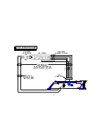
Audiovox AMP-590A Owner'S Manual Download Page 10

PWR

R

L

LOW INPUT

HIGH LEVEL GAIN

MIN MAX

POWER

BATT

GND

REM

LEFT

RIGHT

LEFT

RIGHT

SPEAKER OUTPUT

FUSE

-8-

OPERATION

After initial set-up, the amplifier should not require any
further adjustment unless there is a change in the car
stereo or speaker system with which it is used.

1

Power Indicator LED

The Power Indicator LED will light to indicate that the
unit is connected to the battery and that the Remote
Turn-On terminal is rec12 volts, thus turning
on the amplifier.

2

Level (Gain) Control

The amplifier is capable of operating from sources
supplying a wide range of input levels. The Level
control should initially be set to the mid-rotation posi-
tion. If it is found that there is not enough output even
when the volume control on the car stereo is at its
maximum setting, adjust the Level control to increase

the output from the system. If, however, there is still
output from the amplifier when the car stereo volume
control is at its minimum setting, or the output level
increases too fast with a small rotation of the volume
control, adjust the Level control to decrease the output
from the system. Once the correct setting is found, this
control should not require any further adjustment.

3

Fuse

The circuitry of the amplifier is protected from damage by
an automotive-type fast-blow fuse. If fuse replacement is
necessary, use only fuses of the same ampere rating as
originally supplied with the unit. The use of fuses with
incorrect ratings may cause serious damage to the
amplifier. If fuses blow consistently, carefully check all
electrical connections to the unit.

1

2

3

Summary of Contents for AMP-590A

Page 1: ...Owner s Owner s Owner s Owner s Owner s Manual Manual Manual Manual Manual ModelAMP 590A 150WattStereoAmplifier...

Page 2: ...128 5412 SHT 2 OF 12 INDEX Specifications 1 Precautions 2 InstallationInstructions 3 Wiring Instructions 4 5 Input Wiring Diagram 6 Output Wiring Diagram 7 Operation 8 Warranty 9...

Page 3: ...es Should you require assistance with the installation or wiring of this unit please call our toll free HELP line at 1 800 645 4994 during the days hours shown Monday Friday Saturday 8 30am 7 00pmEast...

Page 4: ...rs will shut off operation until it has cooled down sufficiently 4 If fuse replacement is necessary use only fuses of the same ampere rating as originally supplied with the unit The use of fuses with...

Page 5: ...surface and mark the locations of the four mounting holes as shown in the illustration 3 Remove the amplifier and drill a 1 8 hole at each of the four locations CAUTION Before drilling the holes look...

Page 6: ...nection is also critical to the correct operation of the amplifier Use a wire of the same gauge as the power connection 18 or thicker and connect it between the ground terminal GND of the amplifier an...

Page 7: ...r high level inputs not both If low level outputs are provided from the car stereo it is recommended that the low level inputs be used for lowest distortion and best performance Use good quality shiel...

Page 8: ...IGH LEVEL OR LOW LEVEL INPUTS NOT BOTH HIGH LEVEL SPEAKER OUTPUTS CAR STEREO RCA TYPE SHIELDED CABLE NOT INCLUDED RIGHT RIGHT LEFT LEFT LOW LEVEL RCA OUTPUTS GREEN WHITE GRAY BROWN LEFT RIGHT BLACK CH...

Page 9: ...LEADS TO CHASSIS GROUND FAILURE TO WIRE CORRECTLY MAY CAUSE DAMAGE TO THE AMPLIFIER USE 18 GAUGE WIRE SEE TEXT CONNECT THIS WIRE LAST EXISTINGSCREWORBOLT CLEAN PAINT RUST DIRT OR GREASE FROM AREA FOR...

Page 10: ...not enough output even when the volume control on the car stereo is at its maximum setting adjust the Level control to increase the output from the system If however there is still output from the amp...

Page 11: ...eglect accident or by removal or defacement of the factory serial number bar code label s THE EXTENT OF THE COMPANY S LIABILITY UNDER THIS WARRANTY IS LIMITED TO THE REPAIR OR REPLACEMENT PROVIDED ABO...

Page 12: ...1998 Audiovox Corp Hauppauge N Y Printed in Korea Form No 128 5412...

Reviews: