Audiovox 1286560 Owner'S Manual Download Page 6

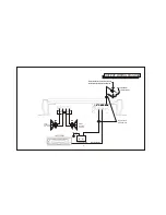
The wiring of your amplifier will depend on the system and speakers you are using but will either be a stereo, mono, or
mixed-mono application. The following pages illustrate the input and output wiring for these types. please refer to the
appropriate diagrams for the system configuration you are using. The power and speakers wire connections for this amplifier
are made via screw tightened terminal blocks. Loosen the screw for the connection to be made and fully insert the wire 
(strip 1/2" of insulation from the end) under the respective screw on the side panel (crimp-on "U" terminals are provided 
to simplify wiring and we recommend their use.). Tighten the screw down to secure the wire.
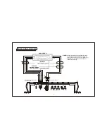
1. Power Connection

The battery terminal (BATT) must be connected directly to the positive terminal of the vehicle battery to provide an
adequate voltage source and minimize noise. Connecting the battery terminal lead to any other point (such as the fuse
block) will reduce the power output and may cause noise and distortion. Use only #10 gauge or thicker (smaller gauge
#) wire for this lead and connect it to the terminal of the battery after all other wiring is completed.

2. Ground Connection

The ground terminal (GND) connection is also critical to the correct operation of the amplifier. Use a wire of the same
gauge as the power connection (#10 or thicker) and connect it between the ground terminal (GND) of the amplifier and
a metal part of the vehicle close to the mounting location. This wire should be as short as possible and any paint or rust
at the grounding point should be scraped away to provide a clean metal surface to which the end of the ground wire can
be screwed or bolted.

3. Remote Turn-On Connection

The amplifier is turned on by ap12 volts to the remote turn-on terminal (REM). The wire lead to this terminal
should be connected to the "Auto-Antenna" lead from the car stereo which will provide the +12 volts only when the car
stereo is turned on. If the car stereo does not provide an Auto-Antenna lead, the remote turn-on lead may be wired to
an "Accessory" or "Radio" terminal in the car's fuse block. This will turn the amplifier on and off with the ignition key,
regardless of whether the car stereo is on or off. The remote turn-on lead does not carry large currents, so #20 gauge
wire may be used for this application.

#10

#10 

-6-

WIRING INSTRUCTIONS

Summary of Contents for 1286560

Page 1: ...OWNER S MANUAL Model AXT 550 500 Watt 2 Channel Bridgeable MOSFET Amplifier...

Page 2: ...INDEX Specifications 3 Precautions 4 Installation Instructions 5 Wiring Instructions 6 7 Input Wiring Diagram 8 Output Wiring Diagram 9 Operation 10 12 Warranty 13...

Page 3: ...Due to continuing improvement Audiovox reserves the right to change features and design without notice 3 This power amplifier has been designed to provide high Quality performance with a minimum of ma...

Page 4: ...off operation until it has cooled down sufficiently 4 If fuse replacement is necessary use only fuses of the same ampere rating as originally supplied with the unit The use of fuses with incorrect rat...

Page 5: ...and mark the locations of the four mounting holes as shown in the illustration 3 Remove the amplifier and drill a 1 8 hole at each of the four locations CAUTION Before drilling the holes look at the u...

Page 6: ...nd connect it to the terminal of the battery after all other wiring is completed 2 Ground Connection The ground terminal GND connection is also critical to the correct operation of the amplifier Use a...

Page 7: ...high level inputs not both If low level outputs are provided from the car stereo it is recommended that the low level inputs be used for lowest distortion and best performance Use good quality shielde...

Page 8: ...ts of car stereo connect only the Positive wires to the amplifier Do not use Negative Output wires insulate ends with tape and leave disconnected HI INPUT HI INPUT GND GND L L R R L L R R R R L L PWR...

Page 9: ...ENNALEAD GROUNDMETAL SECTIONOFVEHICLE EXISTINGSCREWORBOLTCLEANPAINT RUST DIRT ORGREASEFROMAREAFORGOODCONNECTION RIGHT SPEAKER 2 8 OHM LEFT SPEAKER 2 8 OHM OUTPUT WIRING DIAGRAM LEFT RIGHT REM BATT GND...

Page 10: ...ons are caused by mis wiring or operation into incorrect speaker loads Re check all wiring and connections if this situation occurs and correct as necessary 2 1 The Power Indicator Lamps will light to...

Page 11: ...dB 4 8 from the system If however there is still output from the amplifier when the car stereo volume control is at its minimum setting or the output level increases too fast with a small rotation of...

Page 12: ...blow fuse If fuse replacement is necessary use only fuses of the of the same ampere rating as originally supplied with the unit The use of fuses with incorrect ratings may cause serious damage to the...

Page 13: ...of the factory serial number bar code label s THE EXTENT OF THE COMPANY S LIABILITY UNDER THIS WARRANTY IS LIMITED TO THE REPAIR OR REPLACEMENT PROVIDED ABOVE AND IN NO EVENT SHALL THE COMPANY S LIAB...

Page 14: ...2003 Audiovox Electronics Corporation Hauppauge N Y C C Printed in Korea 128 6560...

Reviews: