background image

Version 6.2 

65 

February 2011 

SIP User's Manual 


3. Web-Based Management 


3.3 

Configuration Tab 

The 

Configuration 

tab on the Navigation bar displays menus in the Navigation tree related 

to device configuration. This tab provides the following main menus: 

„


System (see ''System Settings'' on page 

65

„


VoIP (see VoIP Settings on page 

83

„


Data (see Data Settings on page 

222


3.3.1 

System Settings 

The 

System 

menu includes the following: 

„


Application Settings item (see ''Configuring Application Settings'' on page 

65

„


Syslog Settings item (see ''Configuring Syslog Settings'' on page 

68

„


Regional Settings item (see ''Configuring Regional Settings'' on page 

69

„


Certificates item (see ''Configuring Certificates'' on page 

69

„


Management submenu (see ''Management Settings'' on page 

73


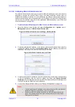
3.3.1.1  Configuring Application Settings 

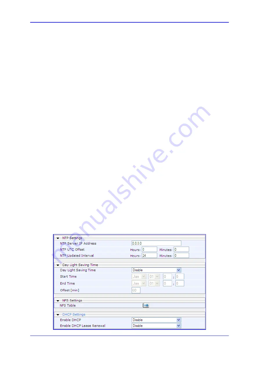
The 'Application Settings' page is used for configuring various application parameters such 
as Network Time Protocol (NTP), daylight saving time, and Network File System (NFS). For 
a description of these parameters, see ''Configuration Parameters Reference'' on page 

653

¾


To configure application settings: 

1. 

Open the 'Application Settings' page (

Configuration

 tab > 

System 

menu > 

Application Settings

). 

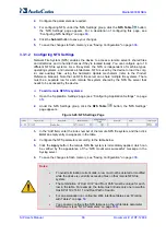
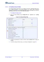
Figure 


3-25: Applications Settings Page 


Summary of Contents for Mediant 800 MSBG

Page 1: ...User s Manual Version 6 2 February 2011 Document LTRT 12804 Mediant 800 MSBG Multi Service Business Gateway SIP Protocol ...

Page 2: ......

Page 3: ... 1 Displaying Navigation Tree in Basic and Full View 46 3 1 5 2 Showing Hiding the Navigation Pane 47 3 1 6 Working with Configuration Pages 48 3 1 6 1 Accessing Pages 48 3 1 6 2 Viewing Parameters 49 3 1 6 3 Modifying and Saving Parameters 51 3 1 6 4 Entering Phone Numbers 52 3 1 6 5 Working with Tables 53 3 1 7 Searching for Configuration Parameters 54 3 1 8 Creating a Login Welcome Message 56 3...

Page 4: ...44 3 5 Status Diagnostics Tab 346 3 5 1 System Status 346 3 5 1 1 Viewing Device Information 346 3 5 1 2 Viewing Ethernet Port Information 348 3 5 1 3 Viewing WAN Port Information 348 3 5 1 4 Carrier Grade Alarms 349 3 5 2 VoIP Status 350 3 5 2 1 Viewing Active IP Interfaces 350 3 5 2 2 Viewing Performance Statistics 350 3 5 2 3 Viewing Call Counters 351 3 5 2 4 Viewing SAS SBC Registered Users 35...

Page 5: ... using an ini File 392 6 3 Restoring Defaults using Hardware Reset Button 392 7 Auxiliary Configuration Files 393 7 1 Call Progress Tones File 393 7 1 1 Distinctive Ringing 396 7 1 2 FXS Distinctive Ringing and Call Waiting Tones per Source Destination Number398 7 2 Prerecorded Tones File 399 7 3 CAS Files 399 7 4 Dial Plan File 400 7 5 User Information File 402 8 IP Telephony Capabilities 405 8 1...

Page 6: ... 9 Three Way Conferencing 465 8 3 8 10 Multilevel Precedence and Preemption 467 8 3 9 SIP Call Routing Examples 469 8 3 9 1 SIP Call Flow Example 469 8 3 9 2 SIP Authentication Example 471 8 3 9 3 Establishing a Call between Two Devices 474 8 3 9 4 SIP Trunking between Enterprise and ITSPs 475 8 3 10 Mapping PSTN Release Cause to SIP Response 478 8 3 11 Querying Device Channel Resources using SIP ...

Page 7: ...lation 579 8 5 Stand Alone Survivability SAS Application 582 8 5 1 SAS Operating Modes 582 8 5 1 1 SAS Outbound Mode 583 8 5 1 2 SAS Redundant Mode 584 8 5 2 SAS Routing 586 8 5 2 1 SAS Routing in Normal State 587 8 5 2 2 SAS Routing in Emergency State 589 8 5 3 SAS Configuration 590 8 5 3 1 General SAS Configuration 590 8 5 3 2 Configuring SAS Outbound Mode 593 8 5 3 3 Configuring SAS Redundant M...

Page 8: ...onfiguring Internal Clock as Clock Source 638 10 2 Release Reason Mapping 638 10 2 1 Reason Header 638 10 2 2 Fixed Mapping of ISDN Release Reason to SIP Response 639 10 2 3 Fixed Mapping of SIP Response to ISDN Release Reason 641 10 3 ISDN Overlap Dialing 642 10 4 ISDN Non Facility Associated Signaling NFAS 643 10 4 1 NFAS Interface ID 644 10 4 2 Working with DMS 100 Switches 644 10 4 3 Creating ...

Page 9: ...Parameters 740 12 12Gateway and IP to IP Parameters 743 12 12 1 Fax and Modem Parameters 743 12 12 2 DTMF and Hook Flash Parameters 745 12 12 3 Digit Collection and Dial Plan Parameters 750 12 12 4 Voice Mail Parameters 753 12 12 5 Supplementary Services Parameters 757 12 12 5 1Caller ID Parameters 757 12 12 5 2Call Waiting Parameters 762 12 12 5 3Call Forwarding Parameters 765 12 12 5 4Message Wa...

Page 10: ...ing Parameters 836 12 12 13 1 Hunt Groups and Routing Parameters 836 12 12 13 2 Alternative Routing Parameters 843 12 12 13 3 Number Manipulation Parameters 847 12 12 13 4 LDAP Parameters 857 12 13SBC Parameters 858 12 14Standalone Survivability Parameters 873 12 15IP Media Parameters 878 12 16Auxiliary and Configuration Files Parameters 881 12 16 1 Auxiliary Configuration File Name Parameters 881...

Page 11: ...9 Figure 2 24 Multiple Interface Table 40 Figure 2 25 Multiple Interfaces with VLANs 40 Figure 2 26 Defining VLANs per LAN Port 40 Figure 3 1 Login Screen 43 Figure 3 2 Areas of the Web Interface GUI 44 Figure 3 3 Reset Displayed on Toolbar 45 Figure 3 4 Navigation Tree 46 Figure 3 5 Toggling Between Navigation Tree Views 47 Figure 3 6 Show Hide Navigation Tree 48 Figure 3 7 Toggling between Basic...

Page 12: ...Figure 3 56 General Media Settings Page 108 Figure 3 57 Analog Settings Page 108 Figure 3 58 SIP Media Realm Table Page 109 Figure 3 59 Media Security Page 111 Figure 3 60 LDAP Settings Page 112 Figure 3 61 Applications Enabling Page 113 Figure 3 62 SRD Settings Page 115 Figure 3 63 SIP Interface Table Page 118 Figure 3 64 IP Group Table 120 Figure 3 65 Proxy Sets Table Page 126 Figure 3 66 SIP Ge...

Page 13: ...gure 3 115 Checkbox for Temporarily Disabling Entry 223 Figure 3 116 WAN Access 225 Figure 3 117 Manual WAN Connection 226 Figure 3 118 PPPoE WAN Connection 226 Figure 3 119 PPTP WAN Connection Type 226 Figure 3 120 L2TP WAN Connection Type 227 Figure 3 121 WAN Access Page for T1 WAN Interface 228 Figure 3 122 PPP Over T1 228 Figure 3 123 Settings Tab for PPP over T1 229 Figure 3 124 PPP Tab 229 F...

Page 14: ...c 263 Figure 3 174 Recreating IPSec Public Key 263 Figure 3 175 IPSec Log Settings 264 Figure 3 176 Configuring VPN PPTP Server 265 Figure 3 177 Configuring VPN L2TP Server 266 Figure 3 178 Adding Users 267 Figure 3 179 Adding a New User 267 Figure 3 180 Defining Outgoing Mail Server 268 Figure 3 181 Adding Users 269 Figure 3 182 Adding a User Group 269 Figure 3 183 Configuring Dynamic DNS DDNS Se...

Page 15: ...ce 298 Figure 3 232 Defining PPPoE Properties 298 Figure 3 233 PPPoE Connection Added Successfully 298 Figure 3 234 Selecting LAN Interfaces for Bridge Connection 300 Figure 3 235 LAN Bridge Successfully Added 301 Figure 3 236 Adding a VLAN Interface 301 Figure 3 237 Assigning VLAN to LAN Ports 302 Figure 3 238 VLAN Added Successfully 302 Figure 3 239 VLAN Interface Advanced Tab 303 Figure 3 240 D...

Page 16: ...Figure 3 290 Editing Network Connection Routing Tab 331 Figure 3 291 Editing Network Connection Advanced Tab 332 Figure 3 292 Maintenance Actions Page 333 Figure 3 293 Reset Confirmation Message Box 335 Figure 3 294 Device Lock Confirmation Message Box 335 Figure 3 295 Load Auxiliary Files Page 338 Figure 3 296 Software Upgrade Key Status Page 340 Figure 3 297 Software Upgrade Key with Multiple S ...

Page 17: ...el for IP to Tel Routing 419 Figure 8 15 Configuring Manipulation for Removing Label 419 Figure 8 16 Prefix to Add Field with Notation 420 Figure 8 17 FXS Device Emulating PSAP using DID Loop Start Lines 421 Figure 8 18 FXO Device Interfacing between E911 Switch and PSAP 424 Figure 8 19 Call Flow for One Stage Dialing 431 Figure 8 20 Call Flow for Two Stage Dialing 432 Figure 8 21 Call Flow for Au...

Page 18: ...ure 8 69 IP Group Classification Rule for LAN Users 555 Figure 8 70 IP to IP Routing Rules 556 Figure 8 71 Survivability Example Setup 557 Figure 8 72 Enabling Proxy Keep Alive 558 Figure 8 73 Configuring IP to IP Routing Rules 559 Figure 8 74 SBC to PSTN Routing Example Setup 560 Figure 8 75 Configuring SIP Interface for PSTN GW 561 Figure 8 76 Defining Device as Proxy Set 562 Figure 8 77 Definin...

Page 19: ... Gateway Application 595 Figure 8 110 Defining Proxy Server for Gateway Application 595 Figure 8 111 Disabling user phone in SIP URL 596 Figure 8 112 Enabling Proxy Server for Gateway Application 596 Figure 8 113 Defining Proxy Servers for Gateway Application 597 Figure 8 114 Disabling user phone in SIP URL 597 Figure 8 115 Manipulating User Part in Incoming REGISTER 599 Figure 8 116 Manipulating ...

Page 20: ... IP Parameters Description 159 Table 3 26 Phone Context Parameters Description 161 Table 3 27 NPI TON Values for ISDN ETSI 162 Table 3 28 Outbound IP Routing Table Parameters 169 Table 3 29 Inbound IP Routing Table Description 173 Table 3 30 Call Forward Table 187 Table 3 31 ISDN Supp Services Table Parameters 192 Table 3 32 Admission Control Parameters 196 Table 3 33 Classification Table Paramete...

Page 21: ...terface Table Example 1 633 Table 9 10 Routing Table Example 1 633 Table 9 11 Multiple Interface Table Example 2 634 Table 9 12 Routing Table Example2 634 Table 9 13 Multiple Interface Table Example 3 635 Table 9 14 Routing Table Example 3 635 Table 10 1 Mapping of ISDN Release Reason to SIP Response 639 Table 10 2 Mapping of SIP Response to ISDN Release Reason 641 Table 10 3 Calling Name Display ...

Page 22: ...772 Table 12 45 Emergency Call Parameters 773 Table 12 46 Call Cut Through Parameters 774 Table 12 47 Automatic Dialing Parameters 775 Table 12 48 DID Parameters 776 Table 12 49 MLPP Parameters 777 Table 12 50 Automatic Dialing Parameters 781 Table 12 51 General PSTN Parameters 783 Table 12 52 TDM Bus and Clock Timing Parameters 787 Table 12 53 CAS Parameters 789 Table 12 54 ISDN Parameters 792 Ta...

Page 23: ...served This document is subject to change without notice Date Published February 21 2011 Trademarks AudioCodes AC AudioCoded Ardito CTI2 CTI CTI Squared HD VoIP HD VoIP Sounds Better InTouch IPmedia Mediant MediaPack NetCoder Netrake Nuera Open Solutions Network OSN Stretto TrunkPack VMAS VoicePacketizer VoIPerfect VoIPerfectHD What s Inside Matters Your Gateway To VoIP and 3GX are trademarks or r...

Page 24: ...d destined to the PSTN PBX i e telephone connected directly or indirectly to the device Tel to IP refers to calls received from the PSTN PBX and destined for the IP network Notes FXO Foreign Exchange Office is the interface replacing the analog telephone and connects to a Public Switched Telephone Network PSTN line from the Central Office CO or to a Private Branch Exchange PBX The FXO is designed ...

Page 25: ...ata Link Control HDLC or or IP over Multilink Point to Point Protocol MLPPP framing The SHDSL WAN connection supports up to four copper wire pairs according to G 991 2 acting as a remote terminal CPE device Both ATM and EFM modes are supported In the ATM mode a variety of protocols are supported including PPPoE PPPoA and RFC 2684 in both bridged Ethernet over ATM and routed IP over ATM variants In...

Page 26: ...can be used as a PBX for Small Office Home Office SOHO users and businesses not equipped with a PBX The FXS modules also support the Analog Lifeline feature enabling an FXS port to connect directly to the PSTN upon power and or network failure The device supports up to four ISDN Basic Rate Interface BRI S T interfaces RJ 45 ports supporting up to eight voice channels These connect ISDN terminal eq...

Page 27: ...of the following main modes VoIP and Data Routing mode VoIP only mode Note This section assumes that you already have IP connectivity to the device i e that you can access its Web interface as described in the Installation Manual 2 2 1 Operating in VoIP and Data Routing Mode If you wish to use the device as a VoIP gateway with data routing functionality you need to configure the following data rou...

Page 28: ... data routing interface s IP address must be in the same subnet as the VoIP and Management interface To define the device s LAN data routing IP address 1 Access the Connections page Configuration tab Data menu Data System Connections Figure 2 1 Connections Page 2 Click the Edit button corresponding to the LAN Switch VLAN 1 connection and then click the Settings tab 3 In the IP Address and Subnet M...

Page 29: ...ick the Edit button corresponding to the LAN Switch VLAN 1 connection 3 From the IP Address Distribution drop down list select DHCP Server 4 Define the IP address pool Figure 2 3 Configuring the DHCP Server 5 Click OK 6 If required refresh the address by disconnecting the cable and then reconnecting it again or by performing the following in Windows command line interface ipconfig release ipconfig...

Page 30: ...ta menu WAN Access Settings 4 From the Connection Type drop down lists select the required connection type for the WAN and then configure the subsequent parameters Figure 2 4 Selecting WAN Connection 5 Configure the WAN interface operating mode for Network Address Port Translation NAPT a Click the Click here for Advanced Settings link and then select the Routing tab the Routing page appears b From...

Page 31: ...and received within the LAN or sent to the WAN via a third party LAN router If a third party router is used as the interface to the WAN then you need to define NAT rules using the NATTranslation parameter to translate the VoIP LAN IP addresses defined in the Multiple Interface table and associated with SIP and media interfaces into global public IP addresses To assign a WAN interface to VoIP traff...

Page 32: ...N bandwidth assigned for example by your Internet Telephony Service Provider ITSP see Defining Total WAN Bandwidth on page 32 Defining traffic shaping classes with the minimum bandwidth guaranteed for VoIP traffic see Defining VoIP Tx Shaping Class on page 33 Assigning the above VoIP traffic class to VoIP RTP media packets and VoIP signaling UDP TCP and TLS traffic matching rules Defining VoIP Tra...

Page 33: ...oIP Tx Traffic Shaping Classes Once you have defined the total bandwidth allocated to the device s WAN interface you need to define a traffic shaping class to reserve a minimum bandwidth e g of 1 Mbps for Tx VoIP traffic SIP signaling and RTP packets out of the total bandwidth e g 5 Mbps To define traffic shaping class for VoIP traffic 1 Open the Traffic Shaping page see Defining Total WAN Bandwid...

Page 34: ...the Queue Priority drop down list select 0 Highest i e the highest priority b In the Bandwidth Reserved field enter 1000 i e 1 Mbps c From the Maximum drop down list select Unlimited d From the Policy drop down list select Priority e Click OK The figure below shows an example of the configured traffic shaping classes for Tx VoIP traffic Figure 2 13 Configured Traffic Shaping for Total WAN and VoIP...

Page 35: ...tched to Traffic Shaping class VOIP Tx Outbound packets sent on this connection will originate from port 5060 Outbound TCP connections from WAN port 5060 5061 sent to any destination must be matched to Traffic Shaping class VOIP Tx Outbound packets on this connection will originate from an arbitrary port but will be destined to port 5060 5061 SIP UDP connections Outbound UDP packets sent from WAN ...

Page 36: ...ic rule for VoIP SIP signaling to the WAN a From the Protocol drop down list select Show All Services to view all protocols and then select SIP SIP is displayed under the Protocol group b From the drop down list appearing below SIP select User Defined the following appears Figure 2 16 Defining Incoming SIP Ports c In the Service Name field enter the service and then click New Server Ports the foll...

Page 37: ...Perform steps 2b through 2e to configure ports for outgoing SIP packets c Under the Operation group select the Set Tx Class Name check box and then from the corresponding drop down list select the traffic shaping class VOIP Tx which you defined for Rx packets in Defining VoIP Tx Shaping Class on page 33 The configured incoming and outgoing SIP ports are shown below Figure 2 19 Traffic Matching Rul...

Page 38: ...RTP and SIP signaling is shown below Figure 2 21 Traffic Matching Rule for WAN Tx Rx RTP and SIP Signaling 2 2 1 6 Configuring Virtual Routing and Forwarding The Virtual Routing and Forwarding VRF Lite feature enables the ability to use a single physical router as several logical routers Each VRF is associated with its own routing table To create fully separated logical routers on the same physica...

Page 39: ...rating in VoIP Only Mode If you wish to use the device for VoIP functionality only i e without data routing functionality you need to disable the data routing interface as described below Note When operating in VoIP only mode do not use the device s WAN port To operate the device as a VoIP gateway only 1 Disconnect the network cable from the WAN port and then connect one of the device s LAN ports ...

Page 40: ...tiple Interface Table With VLANs a In the Multiple Interface table define multiple IP network interfaces each with a unique VLAN ID e g OAMP interface with VLAN ID 501 Media interface with VLAN ID 2012 and Control interface with VLAN ID 2014 Figure 2 25 Multiple Interfaces with VLANs b Define VLANs for each port In the Connections page Configuration tab Data menu Data Settings Connections click th...

Page 41: ...rious security mechanisms such as login user name and password read write privileges and limiting access to specific IP addresses Notes For a detailed description of all the parameters in the Web interface see Configuration Parameters Reference on page 653 The parameters in the Web interface can alternatively be configured using their corresponding ini file parameters which are enclosed in square ...

Page 42: ...ers Microsoft Internet Explorer version 6 0 or later Mozilla Firefox version 2 5 or later Recommended screen resolutions 1024 x 768 pixels or 1280 x 1024 pixels Note Your Web browser must be JavaScript enabled to access the Web interface 3 1 2 Accessing the Web Interface The Web interface can be opened using any standard Web browser see Computer Requirements on page 42 When initially accessing the...

Page 43: ...tailed description of the Home page see Using the Home Page on page 59 Note If access to the device s Web interface is denied Unauthorized due to Microsoft Internet Explorer security settings perform the following 1 Delete all cookies in the Temporary Internet Files folder If this does not resolve the problem the security settings may need to be altered continue with Step 2 2 In Internet Explorer ...

Page 44: ...responding Web interface parameters see Searching for Configuration Parameters on page 54 Navigation tree Displays the elements pertaining to the tab selected on the Navigation bar tree like structure of the configuration menus or Search engine Work pane Displays configuration pages where configuration is performed see Working with Configuration Pages on page 48 3 1 4 Toolbar The toolbar provides ...

Page 45: ...e Getting Help on page 57 Log off Logs off a session with the Web interface see Logging Off the Web Interface on page 58 Note If you modify parameters that take effect only after a device reset after you click the Submit button the toolbar displays the word Reset in red color as shown in the figure below This is a reminder to later save burn your settings to flash memory and reset the device Figur...

Page 46: ... menus and submenus 2 Select the required page item the page opens in the Work pane 3 1 5 1 Displaying Navigation Tree in Basic and Full View You can view an expanded or reduced Navigation tree display regarding the number of listed menus and submenus This is relevant when using the configuration tabs Configuration Maintenance and Status Diagnostics on the Navigation bar The Navigation tree menu c...

Page 47: ...n to provide more space for elements displayed in the Work pane This is especially useful when the Work pane displays a page with a table that s wider than the Work pane and to view the all the columns you need to use scroll bars The arrow button located just below the Navigation bar is used to hide and show the Navigation pane To hide the Navigation pane click the left pointing arrow the pane is ...

Page 48: ... To open a configuration page in the Work pane 1 On the Navigation bar click the required tab Configuration see Configuration Tab on page 65 Maintenance see Maintenance Tab on page 333 Status Diagnostics see Status Diagnostics Tab on page 346 The menus of the selected tab appear in the Navigation tree 2 In the Navigation tree drill down to the required page item the page opens in the Work pane You...

Page 49: ...ad only if your Web user account s access level is low see Configuring the Web User Accounts on page 73 If a page is read only Read Only Mode is displayed at the bottom of the page 3 1 6 2 Viewing Parameters For convenience some pages allow you to view a reduced or expanded display of parameters A reduced display allows you to easily identify required parameters enabling you to quickly configure y...

Page 50: ...st button with up pointing arrow click this button to show only common basic parameters The figure below shows an example of a page displaying basic parameters only and then showing advanced parameters as well using the Advanced Parameter List button Figure 3 7 Toggling between Basic and Advanced View For ease of identification the basic parameters are displayed with a darker blue color background...

Page 51: ...ow indicating that it can be collapsed or expanded when clicked respectively Figure 3 8 Expanding and Collapsing Parameter Groups 3 1 6 3 Modifying and Saving Parameters When you change parameter values on a page the Edit symbol appears to the right of these parameters This is especially useful for indicating the parameters that you have currently modified before applying the changes After you sav...

Page 52: ...u need to save burn them to the device s non volatile memory i e flash see Saving Configuration on page 336 If you modify a parameter value and then attempt to navigate away from the page without clicking Submit a message box appears notifying you of this Click Yes to save your modifications or No to ignore them If you enter an invalid parameter value e g not in the range of permitted values and t...

Page 53: ...s in the table Figure 3 11 Adding an Index Entry to a Table 2 Click Apply to save the index entry Notes Before you can add another index entry you must ensure that you have applied the previously added index entry by clicking Apply If you leave the Add field blank and then click Add Index the existing index entries are all incremented by one and the newly added index entry is assigned the index 0 ...

Page 54: ...en the index entry 4 is re assigned index number 1 and the index entry 6 is re assigned index number 2 Figure 3 12 Compacting a Web Interface Table To delete an existing index table entry 1 In the Index column select the index corresponding to the table row that you want to delete 2 Click Delete the table row is removed from the table 3 1 7 Searching for Configuration Parameters The Web interface ...

Page 55: ...wn list to select the string saved from a previous search 3 Click Search a list of located parameters based on your search appears in the Navigation pane Each searched result displays the following ini file parameter name Link in green to its location page in the Web interface Brief description of the parameter 4 In the searched list click the required parameter link in green to open the page in w...

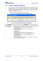
Page 56: ...a Welcome message is shown in the figure below Figure 3 14 User Defined Web Welcome Message after Login Table 3 2 ini File Parameter for Welcome Login Message Parameter Description WelcomeMessage Defines the Welcome message that appears after a successful login to the Web interface The format of this parameter is as follows WelcomeMessage FORMAT WelcomeMessage_Index WelcomeMessage_Text WelcomeMess...

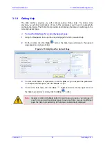
Page 57: ...page for which you want Help 2 On the toolbar click the Help button the Help topic pertaining to the opened page appears as shown below Figure 3 15 Help Topic for Current Page 3 To view a description of a parameter click the plus sign to expand the parameter To collapse the description click the minus sign 4 To close the Help topic click the close button located on the top right corner of the Help...

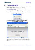
Page 58: ...counts To log off the Web interface 1 On the toolbar click the Log Off button the Log Off confirmation message box appears Figure 3 16 Log Off Confirmation Box 2 Click OK the Web session is logged off and the Log In button appears Figure 3 17 Web Session Logged Off To log in again simply click the Log In button and then in the Enter Network Password dialog box enter your user name and password see...

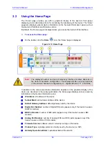
Page 59: ... depends on the ordered hardware configuration i e Gigabit Ethernet T1 or SHDSL In addition to the color coded status information depicted on the graphical display of the device as described in the subsequent table the Home page displays various read only information in the General Information pane IP Address IP address of the device Subnet Mask subnet mask address of the device Default Gateway Ad...

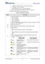
Page 60: ...AL i e E1 T1 PRI and BRI 4 Module status icon green Module has been inserted or is correctly configured gray Module was removed Reserved is displayed alongside the module s name red Module failure Failure is displayed instead of the module s name 5 Port trunk or channel status icon Icon Trunk Description Digital Module Channel Description Analog Modules gray Disable Trunk not configured not in use...

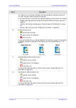
Page 61: ...2 6 WAN port status icons green link is working gray link is not configured red link error To view port information see Viewing WAN Port Information on page 348 Depending on ordered hardware configuration the WAN port can be Gigabit Ethernet T1 or SHDSL Gigabit Ethernet T1 WAN SHDSL One Port Two Ports Four Ports 7 Gigabit Ethernet LAN port status icons green link is working gray link is not config...

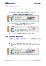
Page 62: ...fo a text box appears Figure 3 20 Text Box for Entering Port Name 3 Type a brief description for the port and then click Apply Port Info 3 2 2 Resetting an Analog Channel The Home page allows you to inactivate reset an FXO or FXS analog channel This is sometimes useful for example when the device FXO is connected to a PBX and the communication between the two can t be disconnected e g when using r...

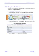
Page 63: ...t such as RTP RTCP and voice settings To view detailed port information 1 Click the port for which you want to view port settings the shortcut menu appears Figure 3 22 Shortcut Menu for Viewing Port Information 2 From the shortcut menu click Port Settings the Basic Channel Information page appears Figure 3 23 Basic Information Screen 3 To view RTP RTCP or voice settings click the relevant button ...

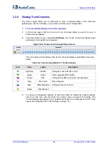
Page 64: ...annels Status Screen The color coding for the status of the trunk s channels status is described in the table below Table 3 4 Color Coding Status for Trunk Channels Icon Color Label Description Light blue Inactive Configured but currently no call Green Active Call in progress RTP traffic Purple SS7 Configured for SS7 Currently not supported Grey Non Voice Not configured Blue ISDN Signaling Configu...

Page 65: ...g Settings item see Configuring Syslog Settings on page 68 Regional Settings item see Configuring Regional Settings on page 69 Certificates item see Configuring Certificates on page 69 Management submenu see Management Settings on page 73 3 3 1 1 Configuring Application Settings The Application Settings page is used for configuring various application parameters such as Network Time Protocol NTP d...

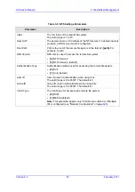
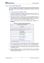
Page 66: ...o be accessed by the device To add remote NFS file systems 1 Open the Application Settings page see Configuring Application Settings on page 65 2 Under the NFS Settings group click the NFS Table button the NFS Settings page appears Figure 3 26 NFS Settings Page 3 In the Add field enter the index number of the remote NFS file system and then click Add an empty entry row appears in the table 4 Confi...

Page 67: ...ersion NFS version used to access the remote file system 2 NFS Version 2 3 NFS Version 3 default Authentication Type Authentication method used for accessing the remote file system 0 Null 1 Unix default User ID User ID used in authentication when using Unix The valid range is 0 to 65537 The default is 0 Group ID Group ID used in authentication when using Unix The valid range is 0 to 65537 The defa...

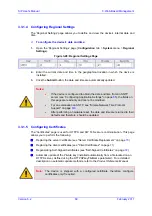
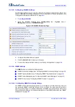
Page 68: ...g Parameters on page 666 For a detailed description on Syslog messages and using third party Syslog servers refer to the Product Reference Manual To configure the Syslog client 1 Open the Syslog Settings page Configuration tab System menu Syslog Settings Figure 3 27 Syslog Settings Page 2 Configure the parameters as required and then click the Submit button to apply your changes 3 To save the chan...

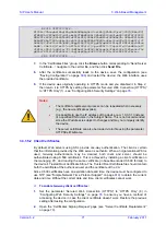
Page 69: ...For an explanation on SNTP see Simple Network Time Protocol Support on page 619 After performing a hardware reset the date and time are returned to their defaults and therefore should be updated 3 3 1 5 Configuring Certificates The Certificates page is used for HTTPS and SIP TLS secure communication This page allows you to perform the following Replacing the server certificate see Server Certifica...

Page 70: ...P and HTTPS 0 see Configuring Web Security Settings on page 76 This ensures that you have a method for accessing the device in case the new certificate doesn t work Restore the previous setting after testing the configuration 3 Open the Certificates Signing Request page Configuration tab System menu Certificates Figure 3 29 Certificates Signing Request Page 4 In the Subject Name field enter the DN...

Page 71: ... device e g 10 3 3 1 instead of a qualified DNS name in the Subject Name This is not recommended since the IP address is subject to changes and may not uniquely identify the device The server certificate can also be loaded via ini file using the parameter HTTPSCertFileName 3 3 1 5 2 Client Certificates By default Web servers using SSL provide one way authentication The client is certain that the i...

Page 72: ...cate can also be loaded via ini file using the parameter HTTPSRootFileName You can enable Online Certificate Status Protocol OCSP on the device to check whether a peer s certificate has been revoked by an OCSP server For further information refer to the Product Reference Manual 3 3 1 5 3 Self Signed Certificates The device is shipped with an operational self signed server certificate The subject n...

Page 73: ...than five minutes the Web session expires and you are once again requested to login with your user name and password Up to five Web users can simultaneously open log in to a session on the device s Web interface Each Web user account is composed of three attributes User name and password enables access login to the Web interface Access level determines the extent of the access i e availability of ...

Page 74: ...accounts attributes 1 Open the Web User Accounts page Configuration tab System menu Web User Accounts Figure 3 30 WEB User Accounts Page for Users with Security Administrator Privileges Note If you are logged into the Web interface as the Security Administrator both Web user accounts are displayed on the Web User Accounts page as shown above If you are logged in with the secondary user account onl...

Page 75: ...ter Network Password dialog box appears requesting you to enter the new password Notes For security it s recommended that you change the default user name and password A Web user with access level Security Administrator can change all attributes of all the Web user accounts Web users with an access level other than Security Administrator can only change their own password and user name To reset th...

Page 76: ...ers as required 3 Click the Submit button to save your changes 4 To save the changes to flash memory see Saving Configuration on page 336 3 3 1 6 3 Configuring Telnet and SSH Settings The Telnet SSH Settings page is used to define Telnet and Secure Shell SSH For a description of these parameters see Web and Telnet Parameters on page 662 To define Telnet and SSH 1 Open the Telnet SSH Settings page ...

Page 77: ... 33 Web Telnet Access List Page Add New Entry 2 To add an authorized IP address in the Add an authorized IP address field enter the required IP address and then click Add New Entry the IP address you entered is added as a new entry to the Web Telnet Access List table Figure 3 34 Web Telnet Access List Table 3 To delete authorized IP addresses select the Delete Row check boxes corresponding to the ...

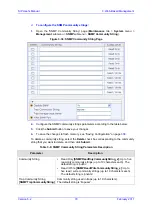
Page 78: ...ee Saving Configuration on page 336 3 3 1 6 6 SNMP Settings The SNMP submenu includes the following items SNMP Community Settings see Configuring SNMP Community Strings on page 78 SNMP Trap Destinations see Configuring SNMP Trap Destinations on page 80 SNMP Trusted Managers see Configuring SNMP Trusted Managers on page 81 SNMP V3 Users see Configuring SNMP V3 Users on page 81 3 3 1 6 6 1 Configuri...

Page 79: ...uration on page 336 To delete a community string select the Delete check box corresponding to the community string that you want to delete and then click Submit Table 3 8 SNMP Community String Parameters Description Parameter Description Community String Read Only SNMPReadOnlyCommunityString_x Up to five read only community strings up to 19 characters each The default string is public Read Write S...

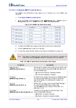
Page 80: ...ert to their defaults Table 3 9 SNMP Trap Destinations Parameters Description Parameter Description SNMP Manager SNMPManagerIsUsed_x Determines the validity of the parameters IP address and port number of the corresponding SNMP Manager used to receive SNMP traps 0 Check box cleared Disabled default 1 Check box selected Enabled IP Address SNMPManagerTableIP_x IP address of the remote host used as a...

Page 81: ...P Trusted Managers Figure 3 38 SNMP Trusted Managers 2 Select the check box corresponding to the SNMP Trusted Manager that you want to enable and for whom you want to define an IP address 3 Define an IP address in dotted decimal notation 4 Click the Submit button to apply your changes 5 To save the changes see Saving Configuration on page 336 3 3 1 6 6 4 Configuring SNMP V3 Users The SNMP v3 Users...

Page 82: ... be unique Authentication Protocol SNMPUsers_AuthProtocol Authentication protocol of the SNMP v3 user 0 None default 1 MD5 2 SHA 1 Privacy Protocol SNMPUsers_PrivProtocol Privacy protocol of the SNMP v3 user 0 None default 1 DES 2 3DES 3 AES 128 4 AES 192 5 AES 256 Authentication Key SNMPUsers_AuthKey Authentication key Keys can be entered in the form of a text password or long hex string Keys are...

Page 83: ...ng Table on page 88 QoS Settings see Configuring QoS Settings on page 89 DNS see DNS on page 91 3 3 2 1 1 Configuring IP Interface Settings The Multiple Interface Table page allows you to configure up to 12 up to 11 Control Media interfaces and a single OAMP interface logical VoIP network interfaces Each interface can be defined with its own IP address unique VLAN ID arbitrary interface name defau...

Page 84: ... VoIP network interfaces configuration see Network Configuration on page 620 You can define firewall rules access list to deny block or permit allow packets received from a specific IP interface configured in this table These rules are configured using the AccessList parameter see Configuring the Access List on page 249 You can view currently active configured IP interfaces in the IP Active Interf...

Page 85: ... applications that are allowed on the specific interface 0 OAMP Only Operations Administration Maintenance and Provisioning OAMP applications e g Web Telnet SSH and SNMP are allowed on the interface 1 Media Only Media i e RTP streams of voice is allowed on the interface 2 Control Only Call Control applications e g SIP are allowed on the interface 3 OAMP Media Only OAMP and Media applications are a...

Page 86: ... IPv4 interfaces For example A subnet mask of 255 0 0 0 is represented by a prefix length of 8 i e 11111111 00000000 00000000 00000000 and a subnet mask of 255 255 255 252 is represented by a prefix length of 30 i e 11111111 11111111 11111111 11111100 The prefix length is a Classless Inter Domain Routing CIDR style presentation of a dotted decimal subnet notation The CIDR style presentation is the...

Page 87: ...be assigned to SIP signaling and media interfaces in the SIP Interface table see Configuring SIP Interface Table on page 117 and SIP Media Realm table see Configuring Media Realms on page 109 where the WAN interface is denoted as WAN Once this association is set VoIP traffic is sent via the WAN and incoming traffic is identified as coming from the WAN The device also automatically configures the r...

Page 88: ...IP Routing Table Page 2 In the Add a new table entry table add a new static routing rule according to the parameters described in the table below 3 Click Add New Entry the new routing rule is added to the IP routing table To delete a routing rule from the table select the Delete Row check box corresponding to the required routing rule and then click Delete Selected Entries Notes You can delete onl...

Page 89: ...e Configuring IP Interface Settings on page 83 Note The IP address of the Gateway IP Address field must be in the same subnet as this interface s IP address Status Read only field displaying the status of the static IP route Active routing rule is used ny the device Inactive routing rule is not applied 3 3 2 1 3 Configuring QoS Settings The Diff Serv Table page is used for configuring the Layer 2 ...

Page 90: ...VLAN priority level 0 7 c Click Apply 3 Configure the desired DiffServ Layer 3 QoS values for the following traffic classes Media Premium QoS this affects Media RTP packets sent by the VoIP towards the LAN Control Premium QoS this affects Control Protocol SIP packets sent by the VoIP towards the LAN Gold QoS this affects HTTP Streaming packets sent by the VoIP towards the LAN Bronze QoS this affec...

Page 91: ...cimal notation for example 10 8 2 255 3 Optionally in the DNS Secondary Server IP enter the IP address of the second DNS server in dotted decimal notation 4 Click the Submit button to apply your changes 5 Save the changes to flash memory refer to Saving Configuration on page 336 3 3 2 1 4 2 Configuring the Internal DNS Table The Internal DNS Table page similar to a DNS resolution translates up to ...

Page 92: ...s to which the host name is translated 5 Click the Submit button to save your changes 6 To save the changes to flash memory see Saving Configuration on page 336 3 3 2 1 4 3 Configuring the Internal SRV Table The Internal SRV Table page resolves host names to DNS A Records Three different A Records can be assigned to each host name Each A Record contains the host name priority weight and port Notes...

Page 93: ...string of up to 31 characters 3 From the Transport Type drop down list select a transport type 4 In the DNS Name 1 field enter the first DNS A Record to which the host name is translated 5 In the Priority Weight and Port fields enter the relevant values 6 Repeat steps 4 through 5 for the second and third DNS names if required 7 Repeat steps 2 through 6 for each entry 8 Click the Submit button to s...

Page 94: ...e 2 Configure the parameters as required 3 Click the Submit button to save your changes 4 Save the changes to flash memory see Saving Configuration on page 336 3 3 2 3 Security The Security Settings submenu allows you to configure various security settings This menu contains the following page items Firewall Settings see Configuring Firewall Settings on page 94 General Security Settings see Config...

Page 95: ...th limitations To block all traffic the following must be set IP address to 0 0 0 0 Prefix length of 0 implies the rule can match any IP address Local port range 0 65535 Protocol Any Action Upon Match block You can also configure the firewall settings using the ini file table parameter AccessList see Security Parameters on page 671 To add firewall rules 1 Open the Firewall Settings page Configurat...

Page 96: ...anges to flash memory see Saving Configuration on page 336 To activate a de activated rule 1 In the Edit Rule column select the de activated rule that you want to activate 2 Click the Activate button the rule is activated To de activate an activated rule 1 In the Edit Rule column select the activated rule that you want to de activate 2 Click the DeActivate button the rule is de activated To delete...

Page 97: ...able i e packets received from that defined in the Source IP field and received on this network interface 0 Disable default 1 Enable Notes If enabled then in the Interface Name field described below select the interface to which the rule is applied If disabled then the rule applies to all interfaces Interface Name AccessList_Interface_ID The network interface to which you want to apply the rule Th...

Page 98: ...nfiguring General Security Settings The General Security Settings page is used to configure various security features For a description of the parameters appearing on this page refer Configuration Parameters Reference on page 653 To configure the general security parameters 1 Open the General Security Settings page Configuration tab VoIP menu Security submenu General Security Settings Figure 3 48 ...

Page 99: ...e inactive stopped i e the Related Trunks field displays the trunk number in green 2 State machine is not in use or is in reset or when it is not related to any trunk If it is related to a trunk you must delete the trunk or de activate Stop the trunk Field values displaying 1 indicate CAS default values In other words CAS state machine values are used The modification of the CAS state machine occu...

Page 100: ...msec units The digit time length must be longer than this value to receive a detection Any number may be used but the value must be less than CasStateMachineDTMFMaxOnDetectionTime The value must be a positive value The default value is 1 use value from CAS state machine MAX Incoming Address Digits CasStateMachineMaxNumOfInco mingAddressDigits Defines the limitation for the maximum address digits t...

Page 101: ...ally the trunk from the PSTN network Upon trunk deactivation the device generates an AIS alarm on that trunk to the far end as a result an RAI alarm signal may be received by the device A subsequent trunk activation by clicking the Activate button reconnects the trunk to the PSTN network and clears the AIS alarm Trunk deactivation is typically used for maintenance such as checking the trunk s phys...

Page 102: ...ilable trunks the scroll bar buttons are unavailable After you have selected a trunk the following is displayed The read only Module ID field displays the module number to which the trunk belongs The read only Trunk ID field displays the selected trunk number The read only Trunk Configuration State displays the state of the trunk Active or Inactive The displayed parameters pertain to the selected ...

Page 103: ...e protocol type is CAS you can assign or modify a dial plan in the Dial Plan field and perform this without stopping the trunk If the trunk can t be stopped because it provides the device s clock assuming the device is synchronized with the E1 T1 clock assign a different E1 T1 trunk to provide the device s clock or enable TDM Bus PSTN Auto Clock in the TDM Bus Settings page see TDM on page 94 To d...

Page 104: ...e For a detailed description of these parameters see Configuration Parameters Reference on page 653 To configure the voice parameters 1 Open the Voice Settings page Configuration tab VoIP menu Media submenu Voice Settings Figure 3 52 Voice Settings Page 2 Configure the Voice parameters as required 3 Click the Submit button to save your changes 4 To save the changes to flash memory see Saving Confi...

Page 105: ...ce on page 653 To configure the fax modem and CID parameters 1 Open the Fax Modem CID Settings page Configuration tab VoIP menu Media submenu Fax Modem CID Settings Figure 3 53 Fax Modem CID Settings Page 2 Configure the parameters as required 3 Click the Submit button to save your changes 4 To save the changes to flash memory see Saving Configuration on page 336 Note Some SIP parameters override ...

Page 106: ...ailed description of the parameters appearing on this page refer to Configuration Parameters Reference on page 653 To configure the RTP RTCP parameters 1 Open the RTP RTCP Settings page Configuration tab VoIP menu Media submenu RTP RTCP Settings Figure 3 54 RTP RTCP Settings Page 2 Configure the parameters as required 3 Click the Submit button to save your changes 4 To save the changes to flash me...

Page 107: ...f the parameters appearing on this page see Configuration Parameters Reference on page 653 To configure the IP media parameters 1 Open the IPMedia Settings page Configuration tab VoIP menu Media submenu IPMedia Settings Figure 3 55 IPMedia Settings Page 2 Configure the parameters as required 3 Click the Submit button to save your changes 4 To save the changes to flash memory see Saving Configurati...

Page 108: ...e Saving Configuration on page 336 3 3 2 5 6 Configuring Analog Settings The Analog Settings page allows you to configure various analog parameters For a detailed description of the parameters appearing on this page see Configuration Parameters Reference on page 653 This page also selects the type USA or Europe of FXS and or FXO coefficient information The FXS coefficient contains the analog telep...

Page 109: ...SRD the IP Group s Media Realm takes precedence For this setting to take effect a device reset is required To define a Media Realm 1 Open the SIP Media Realm Table page Configuration tab VoIP menu Media submenu Media Realm Configuration Figure 3 58 SIP Media Realm Table Page 2 In the Add Index field enter the required index number and then click Add Index 3 Configure the parameters according to th...

Page 110: ...orts must not overlap Number of Media Session Legs CpMediaRealm_MediaSessionLeg Defines the number of media sessions associated with the range of ports This is the number of media sessions available in the port range For example 100 ports correspond to 10 media sessions since ports are allocated in chunks of 10 Port Range End CpMediaRealm_PortRangeEnd Read only field displaying the ending port for...

Page 111: ...of the parameters appearing on this page see Configuration Parameters Reference on page 653 To configure media security 1 Open the Media Security page Configuration tab VoIP menu Media submenu Media Security Figure 3 59 Media Security Page 2 Configure the parameters as required 3 Click the Submit button to save your changes 4 To save the changes to flash memory see Saving Configuration on page 336...

Page 112: ...ration Parameters Reference on page 653 For an overview of LDAP see Routing Based on LDAP Active Directory Queries on page 605 To configure the LDAP parameters 1 Open the LDAP Settings page Configuration tab VoIP menu Services submenu LDAP Settings Figure 3 60 LDAP Settings Page The read only LDAP Server Status field displays one of the following possibilities Not Applicable Connection Broken Conn...

Page 113: ...le release For enabling an application a device reset is required To enable an application 1 Open the Applications Enabling page Configuration tab VoIP menu Applications Enabling submenu Applications Enabling Figure 3 61 Applications Enabling Page 2 Save the changes to the device s flash memory and then reset the device see Saving Configuration on page 336 3 3 2 8 Control Network The Control Netwo...

Page 114: ...ed with a SIP Interface and RTP media associated with a Media Realm for multiple Layer 3 networks Due to the B2BUA nature of the SBC application different interfaces can be assigned to each leg of the call and between the LAN and WAN side Can operate with multiple gateway customers that may reside either in the same or in different Layer 3 networks as the device This allows separation of signaling...

Page 115: ...he table below 3 Click the Submit button to apply your changes 4 To save the changes to flash memory see Saving Configuration on page 336 Note The SRD Settings page also allows you to define a SIP Interface in the SIP Interface table instead of navigating to the SIP Interface Table page as described in Configuring SIP Interface Table on page 117 Table 3 16 SRD Table Parameters Parameter Descriptio...

Page 116: ... not required When two UA s pertain to the same SRD and this parameter is set to 1 and one of the UA s is defined as a foreign user example follow me service located on the WAN while the other UA is located on the LAN then calls between these two UA s can t be established until this parameter is set to 0 as the device doesn t interfere in the SIP signaling In other words parameters such as IP addr...

Page 117: ...all leg i e each SIP user agent communicates with a specific SRD SIP Interfaces can be used for the following Creating different SIP signaling ports listening UDP TCP and TLS and the UDP source ports for a single interface or for multiple interfaces Differentiating between different device applications i e SAS Gateway IP2IP and SBC by creating SIP interfaces per application Separating signaling tr...

Page 118: ... see Configuring IP Interface Settings on page 83 To create a SIP interface on the WAN interface enter the string WAN This WAN interface is selected in the Multiple Interface table see Configuring IP Interface Settings on page 83 or use the WANInterfaceName parameter which is the WAN interface address as defined in WAN Access Settings on page 224 If VLANs are defined for the WAN interface and one ...

Page 119: ...IP Group Served IP Group e g corporate IP PBX with another IP Group Serving IP Group e g ITSP This is configured in the Account see Configuring Account Table on page 133 Call routing rules Outgoing IP calls IP to IP or Tel to Tel used to identify the source of the call and used as the destination for the outgoing IP call defined in the Outbound IP Routing Table For Tel to IP calls the IP Group Ser...

Page 120: ...his IP Group is set to default values and is used by the device when IP Groups are not implemented You can also configure the IP Groups table using the ini file table parameter IPGroup see SIP Configuration Parameters To configure IP Groups 1 Open the IP Group Table page Configuration tab VoIP menu Control Network submenu IP Group Table Figure 3 64 IP Group Table 2 Configure the IP group parameter...

Page 121: ... database by using the request URI for an entry that matches a registered AOR or Contact Once an entry is found the IP destination is obtained from this entry and a SIP request is sent to the destination The device also supports NAT traversal for the SIP clients that are behind NAT In this case the device must be defined with a global IP address 2 GATEWAY This is applicable only to the SBC applica...

Page 122: ...VITE messages received from the IP Group If not specified the value of the global parameter ProxyName see Configuring Proxy and Registration Parameters on page 136 is used instead The value range is a string of up to 100 characters The default is an empty field Note If the IP Group is of type USER this parameter is used internally as a host name in the Request URI for Tel to IP initiated calls For...

Page 123: ...ting mode for outgoing SIP INVITE messages 1 Not Configured The routing is according to the selected Serving IP Group If no Serving IP Group is selected the device routes the call according to the Outbound IP Routing Table see Configuring the Outbound IP Routing Table Default 0 Routing Table The device routes the call according to the Outbound IP Routing Table 1 Serving IP Group The device sends t...

Page 124: ...ToProxy is set to 1 Enable Survivability IPGroup_EnableSurvivability Determines whether Survivability mode is enabled for USER type IP Groups 0 Disable default 1 Enable if Necessary Survivability mode is enabled The device records in its database the registration messages sent by the clients belonging to the USER type IP Group If communication with the Serving IP Group e g IP PBX fails the USER ty...

Page 125: ...n according to the device s database fails for locating whether the INVITE arrived from a registered user The classification proceeds with checking whether the INVITE s IP address if host names then according to the dynamically resolved IP address list is defined in the IP Group s Proxy Set ID in the Proxy Set table If the IP address is listed then the INVITE is assigned to this IP Group Notes Thi...

Page 126: ... other words the Proxy Set represents the destination of the call Typically for IP to IP call routing at least two Proxy Sets are defined for call destination one for each leg IP Group of the call i e both directions For example one Proxy Set for the Internet Telephony Service provider ITSP interfacing with one leg of the device and another Proxy Set for the second SIP entity e g ITSP interfacing ...

Page 127: ...oup ID as defined in the Hunt Group Settings table According to the Outbound IP Routing Table if the parameter PreferRouteTable is set to 1 To the default Proxy Typically when IP Groups are used there is no need to use the default Proxy and all routing and registration rules can be configured using IP Groups and the Account tables see Configuring Account Table on page 133 Proxy Address ProxyIp_IpA...

Page 128: ...le default 1 Using Options Enables Keep Alive with Proxy using SIP OPTIONS messages 2 Using Register Enables Keep Alive with Proxy using SIP REGISTER messages If set to Using Options the SIP OPTIONS message is sent every user defined interval configured by the parameter ProxyKeepAliveTime If set to Using Register the SIP REGISTER message is sent every user defined interval configured by the Regist...

Page 129: ...AliveTime tags each entry as offline or online Load balancing is only performed on Proxy servers that are tagged as online All outgoing messages are equally distributed across the list of IP addresses REGISTER messages are also distributed unless a RegistrarIP is configured The IP addresses list is refreshed according to ProxyIPListRefreshTime If a change in the order of the entries in the list oc...

Page 130: ...ed with the Proxy Set ID Notes For this parameter to take effect a device reset is required If no SRD is defined for this parameter by default SRD ID 0 is associated with the Proxy Set Web EMS Classification Input ClassificationInput Classifies an IP call to a Proxy Set based on either its IP address or based on its IP address port and transport type 0 Compare only IP IP call classified to Proxy S...

Page 131: ... 3 Web Based Management To configure general SIP parameters 1 Open the SIP General Parameters page Configuration tab VoIP menu SIP Definitions submenu General Parameters Figure 3 66 SIP General Parameters Page 2 Configure the parameters as required ...

Page 132: ...nced Parameters The Advanced Parameters page allows you to configure advanced SIP control parameters For a description of the parameters appearing on this page see Configuration Parameters Reference on page 653 To configure advanced general protocol parameters 1 Open the Advanced Parameters page Configuration tab VoIP menu SIP Definitions submenu Advanced Parameters Figure 3 67 SIP General Paramet...

Page 133: ...n the Account table with the same Served Hunt Group or Served IP Group but with different Serving IP Groups user name password host name and contact user values When using the Account table to register a Trunk Group to a Proxy server if all trunks pertaining to the Trunk Group are down the device un registers the trunks If any trunk belonging to the Trunk Group is returned to service the device re...

Page 134: ... 119 to where the REGISTER requests if enabled are sent or authentication is performed The actual destination to where the REGISTER requests are sent is the IP address defined for the Proxy Set ID see Configuring Proxy Sets Table on page 126 associated with the IP Group This occurs only in the following conditions The parameter Registration Mode is set to Per Account in the Hunt Group Settings tab...

Page 135: ... specific Hunt Group The Host Name i e host name in SIP From To headers and Contact User user in From To and Contact headers are taken from this table upon a successful registration See the example below REGISTER sip xyz SIP 2 0 Via SIP 2 0 UDP 10 33 37 78 branch z9hG4bKac1397582418 From sip ContactUser HostName tag 1c1397576231 To sip ContactUser HostName Call ID 1397568957261200022256 10 33 37 7...

Page 136: ...ns the source party number Application Type Account_ApplicationType Defines the application type 0 GW IP2IP Gateway and IP to IP application default The IP to IP application will be supported in the next applicable release 2 SBC SBC application 3 3 2 9 4 Configuring Proxy and Registration Parameters The Proxy Registration page allows you to configure the Proxy server and registration parameters Fo...

Page 137: ...configure the Proxy and registration parameters 1 Open the Proxy Registration page Configuration tab VoIP menu SIP Definitions submenu Proxy Registration Figure 3 69 Proxy Registration Page 2 Configure the parameters as required 3 Click the Submit button to save your changes ...

Page 138: ...to customize these parameters or turn them on or off per source or destination routing and or per the device s trunks channels For example specific E1 T1 spans can be assigned a Profile that always uses G 711 Each call can be associated with one or two Profiles Tel Profile and or IP Profile If both IP and Tel Profiles apply to the same call the coders and other common parameters of the preferred P...

Page 139: ...0 OK SDP even if multiple coders are defined The device always uses the packetization time requested by the remote side for sending RTP packets For G 729 it s also possible to select silence suppression without adaptations If the coder G 729 is selected with silence suppression is disabled the device includes annexb no in the SDP of the relevant SIP messages If silence suppression is enabled or se...

Page 140: ...oder Groups The Coder Group Settings page allows you to define up to four different Coder Groups These Coder Groups can be assigned to Tel Profiles see Configuring Tel Profiles on page 141 and or IP Profiles see Configuring IP Profiles on page 143 For each Coder Group you can define up to ten coders where the first coder in the table takes precedence over the second coder and so on The first coder...

Page 141: ...0 payload types of well known coders cannot be modified 7 From the Silence Suppression drop down list enable or disable the silence suppression option for the coder you selected 8 Repeat steps 3 through 7 for the next coders optional 9 Repeat steps 2 through 8 for the next coder group optional 10 Click the Submit button to save your changes 11 To save the changes to flash memory see Saving Configu...

Page 142: ... Configuration tab VoIP menu Coders And Profiles submenu Tel Profile Settings Figure 3 72 Tel Profile Settings Page 2 From the Profile ID drop down list select the Tel Profile identification number you want to configure 3 In the Profile Name field enter an arbitrary name that enables you to easily identify the Tel Profile ...

Page 143: ...7 Repeat steps 2 through 6 to configure additional Tel Profiles optional 8 Click the Submit button to save your changes 9 To save the changes to flash memory see Saving Configuration on page 336 3 3 2 10 4Configuring IP Profiles The IP Profile Settings page allows you to define up to nine IP Profiles You can later assign these IP Profiles to other configuration entities Outbound IP Routing Table s...

Page 144: ...ings page Configuration tab VoIP menu Coders And Profiles submenu IP Profile Settings Figure 3 73 IP Profile Settings Page 2 From the Profile ID drop down list select an identification number for the IP Profile 3 In the Profile Name field enter an arbitrary name that allows you to easily identify the IP Profile ...

Page 145: ...roups you defined in the Coder Group Settings page see Configuring Coder Groups on page 140 7 Repeat steps 2 through 6 for the next IP Profiles optional 8 Click the Submit button to save your changes 9 To save the changes to flash memory see Saving Configuration on page 336 3 3 2 11 GW and IP to IP The GW and IP to IP submenu configures the gateway as well as IP to IP parameters and includes the f...

Page 146: ...74 Hunt Group Table Page 2 Configure the Hunt Group according to the table below 3 Click the Submit button to save your changes 4 To save the changes to the flash memory see Saving Configuration on page 336 Table 3 21 Hunt Group Table Parameters Parameter Description Module TrunkGroup_Module The module i e FXS FXO PRI or BRI for which you want to define the Hunt Group From Trunk TrunkGroup_FirstTr...

Page 147: ...or a range of channels e g 1 4 then the phone number must end with a number e g user1 This field is optional for BRI PRI interfaces The logical numbers defined in this field are used when an incoming PSTN PBX call doesn t contain the calling number or called number the latter being determined by the ReplaceEmptyDstWithPortNumber parameter These numbers are used to replace them Trunk Group ID Trunk...

Page 148: ...e 836 To configure the Hunt Group Settings table 1 Open the Hunt Group Settings page Configuration tab VoIP menu GW and IP to IP submenu Hunt Group submenu Hunt Group Settings Figure 3 75 Hunt Group Settings Page 2 From the Index drop down list select the range of entries that you want to edit 3 Configure the Hunt Group according to the table below 4 Click the Submit button to save your changes 5 ...

Page 149: ...nkGroupSettings_Registratio nMode Registration method for the Hunt Group 1 Per Gateway Single registration for the entire device default This mode is applicable only if a default Proxy or Registrar IP are configured and Registration is enabled i e parameter IsRegisterUsed is set to 1 In this mode the SIP URI user part in the From To and Contact headers is set to the value of the global registratio...

Page 150: ...unt registration modes is set to the value of the field SIP Group Name defined in the IP Group table see Configuring IP Groups on page 119 If no Serving IP Group ID is selected the INVITE messages are sent to the default Proxy or according to the Outbound IP Routing Table see Configuring Outbound IP Routing Table on page 165 Note If the parameter PreferRouteTable is set to 1 see Configuring Proxy ...

Page 151: ...ing Redirect Number Tel to IP on page 158 Phone Context see Mapping NPI TON to SIP Phone Context on page 160 Release Cause Mapping see Configuring Release Cause Mapping on page 162 3 3 2 11 2 1 Configuring General Settings The General Settings page allows you to configure general manipulation parameters For a description of the parameters appearing on this page see Configuration Parameters Referen...

Page 152: ...ries IP to Tel calls Destination Phone Number Manipulation Table for IP to Tel Calls NumberMapIP2Tel ini file parameter up to 100 entries Source Phone Number Manipulation Table for IP to Tel Calls SourceNumberMapIP2Tel ini file parameter up to 120 entries The device searches a matching manipulation rule starting from the first entry i e top of the table In other words a rule at the top of the tabl...

Page 153: ...on number prefix and or source number prefix match the values defined in the Source IP Address Source Trunk Group Source IP Group Destination Prefix and Source Prefix fields respectively The number manipulation can be performed using a combination of each of the above criteria or using each criterion independently For available notations representing multiple numbers digits for destination and sou...

Page 154: ...Tel to IP calls To denote all Hunt Groups leave this field empty Notes The value 1 indicates that this field is ignored in the rule This parameter is available only in the Source Phone Number Manipulation Table for Tel IP Calls and Destination Phone Number Manipulation Table for Tel IP Calls pages For IP to IP call routing this parameter is not required i e leave the field empty Source IP Group Th...

Page 155: ...digits to remove from the right of the telephone number prefix For example if you enter 3 and the phone number is 5551234 the new phone number is 5551 Web Prefix to Add EMS Prefix Suffix To Add The number or string that you want added to the front of the telephone number For example if you enter 9 and the phone number is 1234 the new number is 91234 Web Suffix to Add EMS Prefix Suffix To Add The n...

Page 156: ...r manipulation If Presentation is set to Restricted and the AssertedIdMode parameter is set to P Asserted the From header in the INVITE message includes the following From anonymous sip anonymous anonymous invalid and privacy id header 3 3 2 11 2 3 Configuring Redirect Number IP to Tel The Redirect Number IP Tel page allows you to configure IP to Tel redirect number manipulation rules This feature...

Page 157: ...hone number is 1234 Web Stripped Digits From Right EMS Remove From Right Number of digits to remove from the right of the telephone number prefix For example if you enter 3 and the phone number is 5551234 the new phone number is 5551 Web EMS Prefix to Add The number or string that you want added to the front of the telephone number For example if you enter 9 and the phone number is 1234 the new nu...

Page 158: ...ault 9 Private 1 E 164 Public 1 Not Configured value received from PSTN IP is used Note For a detailed list of the available NPI TON values see Numbering Plans and Type of Number on page 162 3 3 2 11 2 4 Configuring Redirect Number Tel to IP The Redirect Number Tel IP page allow you to configure Tel to IP Redirect Number manipulation rules This feature manipulates the prefix of the redirect number...

Page 159: ...hat this field is ignored in the rule For IP to IP call routing this parameter is not required i e leave the field empty Source IP Group The IP Group from where the IP to IP call originated Typically the IP Group of an incoming INVITE is determined classified using the Inbound IP Routing Table If not used i e any IP Group simply leave the field empty Notes The value 1 indicates that it is ignored ...

Page 160: ...ing From anonymous sip anonymous anonymous invalid and privacy id header 3 3 2 11 2 5 Mapping NPI TON to SIP Phone Context The Phone Context Table page allows you to map Numbering Plan Indication NPI and Type of Number TON to the SIP Phone Context parameter When a call is received from the ISDN Tel the NPI and TON are compared against the table and the matching Phone Context value is used in the o...

Page 161: ...ether the received Phone Context parameter is added as a prefix to the outgoing ISDN SETUP message digital interfaces with Called and Calling numbers 0 Disable default 1 Enable NPI Select the Number Plan assigned to this entry 0 Unknown default 1 E 164 Public 9 Private For a detailed list of the available NPI TON values see Numbering Plans and Type of Number on page 162 TON Select the Type of Numb...

Page 162: ...known 0 A private number but with no further information about the numbering plan Level 2 Regional 1 Level 1 Regional 2 A private number with a location e g 3932200 PISN Specific 3 Level 0 Regional local 4 A private local extension number e g 2200 For NI 2 and DMS 100 ISDN variants the valid combinations of TON and NPI for calling and called numbers include Plan Type 0 0 Unknown Unknown 1 1 Intern...

Page 163: ...Release Cause Mapping Figure 3 81 Release Cause Mapping Page 2 In the Release Cause Mapping from ISDN to SIP group map different Q 850 Release Causes to SIP Responses 3 In the Release Cause Mapping from SIP to ISDN group map different SIP Responses to Q 850 Release Causes 4 Click the Submit button to save your changes 5 To save the changes so they are available after a power fail see Saving Config...

Page 164: ...age 174 Forward on Busy Trunk see Configuring Call Forward upon Busy Trunk on page 176 3 3 2 11 3 1 Configuring General Routing Parameters The Routing General Parameters page allows you to configure general routing parameters For a description of these parameters see Configuration Parameters Reference on page 653 To configure general routing parameters 1 Open the Routing General Parameters page Co...

Page 165: ...s destination If the number dialed does not match the characteristics the call is not made The destination can be any of the following IP address Fully Qualified Domain Name FQDN E 164 Number Mapping ENUM Lightweight Directory Access Protocol LDAP for a description see Routing Based on LDAP Active Directory Queries on page 605 IP Group the call is routed to the Proxy Set IP address or SRD associat...

Page 166: ...ot exist in the table or a Call Restriction see below routing rule is applied the call is released Obtain different SIP URI host names per called number Assign IP Profiles to calls Note For this table to take precedence over a proxy for routing calls you need to set the parameter PreferRouteTable to 1 The device checks the Destination IP Address field in this table for a match with the outgoing ca...

Page 167: ... Alternative routing is typically implemented when there is no response to an INVITE message after INVITE re transmissions The device then issues an internal 408 No Response implicit Release Reason If this reason is defined see Configuring Alternative Routing Reasons on page 174 the device immediately initiates a call to the alternative destination using the next matching entry in this routing tab...

Page 168: ... in turn is associated with a Proxy Set ID providing the IP address Rule 3 If the called phone number prefix is 5 7 8 or 9 and the caller belongs to Hunt Group ID 1 the call is sent to domain com Rule 4 For all callers if the called phone number prefix is 00 the call is rejected discarded Rule 5 For all callers if the called phone number prefix is 6 the call is sent to SRD 2 i e Proxy Set associat...

Page 169: ...n such a scenario this routing table is used only if the parameter PreferRouteTable is set to 1 Web Src Host Prefix EMS Source Host Prefix The prefix of the SIP Request URI host name in the From header of the incoming SIP INVITE message If this routing rule is not required leave the field empty Notes To denote any prefix use the asterisk symbol This parameter is applicable only for IP to IP routin...

Page 170: ... and in the Dest IP Address field enter 0 0 0 0 For routing calls between phones connected to the device i e local routing enter the device s IP address When the device s IP address is unknown e g when DHCP is used enter IP address 127 0 0 1 When using domain names you must enter the DNS server s IP address or alternatively define these names in the Internal DNS Table see Configuring the Internal ...

Page 171: ...the IP Group table This parameter is used as the Serving IP Group in the Account table for acquiring authentication user password for this call see Configuring Account Table on page 133 For defining Proxy Set ID s see Configuring Proxy Sets Table on page 126 Dest SRD The SRD to where you want to route the call The actual destination is defined by the Proxy Set associated with the SRD This allows y...

Page 172: ...tch a table entry the rule is used to route the call One or more characteristics can be defined for the rule such as source destination Request URI host name prefix source calling destination called telephone number prefix and source IP address from where call received Destination user defined destination If the call matches the characteristics the device routes the call to this destination The de...

Page 173: ...n page 336 Table 3 29 Inbound IP Routing Table Description Parameter Description IP to Tel Routing Mode RouteModeIP2Tel Determines whether to route the incoming IP call before or after manipulation of destination number configured in Configuring Number Manipulation Tables on page 152 0 Route calls before manipulation Incoming IP calls are routed before number manipulation default 1 Route calls aft...

Page 174: ...les on page 143 to assign to the call Source IP Group ID For IP to Tel calls The IP Group associated with the incoming IP call This is the IP Group from where the INVITE message originated This IP Group can later be used as the Serving IP Group in the Account table for obtaining authentication user name password for this call see Configuring Account Table on page 133 For IP to IP calls The IP Grou...

Page 175: ... routing table set the parameter RedundantRoutingMode to 1 default The reasons for alternative routing for Tel to IP calls also apply for Proxies if the parameter RedundantRoutingMode is set to 2 You can also configure alternative routing using the ini file table parameters AltRouteCauseTel2IP and AltRouteCauseIP2Tel see Number Manipulation and Routing Parameters on page 836 To configure reasons f...

Page 176: ...ginal destination number is replaced by the user part The device forwards calls using this table only if no alternative IP to Tel routing rule has been configured or alternative routing fails and one of the following reasons included in the SIP Diversion header of 3xx messages exists For digital interfaces out of service all trunks are unavailable disconnected unavailable For digital interfaces Al...

Page 177: ...g on this page see Configuration Parameters Reference on page 653 To configure the DTMF and dialing parameters 1 Open the DTMF Dialing page Configuration tab VoIP menu GW and IP to IP submenu DTMF Supplementary submenu DTMF Dialing Figure 3 88 DTMF Dialing Page 2 Configure the parameters as required 3 Click the Submit button to save your changes 4 To save the changes to flash memory see Saving Con...

Page 178: ...P submenu DTMF Supplementary submenu Supplementary Services Figure 3 89 Supplementary Services Page 2 Configure the parameters as required 3 Click the Submit button to save your changes or click the Subscribe to MWI or Unsubscribe to MWI buttons to save your changes and to subscribe unsubscribe to the MWI server 4 To save the changes to flash memory see Saving Configuration on page 336 ...

Page 179: ...s on page 188 Call Waiting see Configuring Call Waiting on page 189 Note The Analog Gateway submenu appears only if the device is installed with an FXS or FXO module 3 3 2 11 5 1 Configuring Keypad Features The Keypad Features page enables you to activate and deactivate the following features directly from the connected telephone s keypad Call Forward see Configuring Call Forward on page 186 Calle...

Page 180: ...bmit button to save your changes 4 To save the changes to the flash memory see Saving Configuration on page 336 3 3 2 11 5 2 Configuring Metering Tones The FXS interfaces can generate 12 16 KHz metering pulses toward the Tel side e g for connection to a pay phone or private meter Tariff pulse rate is determined according to the device s Charge Codes table This capability enables users to define di...

Page 181: ...rs as required For a description of the parameters appearing on this page see Configuration Parameters Reference on page 653 3 Click the Submit button to save your changes 4 To save the changes to the flash memory see Saving Configuration on page 336 If you set the Generate Metering Tones parameter to Internal Table access the Charge Codes Table page by clicking the Charge Codes Table button For a...

Page 182: ...ays starts at midnight 00 It is mandatory that the last time period of each rule ends at midnight 00 This prevents undefined time frames in a day The device selects the time period by comparing the device s current time to the end time of each time period of the selected Charge Code The device generates the Number of Pulses on Answer once the call is connected and from that point on it generates a...

Page 183: ... and password for authenticating each device port Authentication is typically used for FXS interfaces but can also be used for FXO interfaces Notes For configuring whether authentication is performed per port or for the entire device use the parameter AuthenticationMode If authentication is for the entire device the configuration on this page is ignored If either the user name or password fields a...

Page 184: ...utomatic Dialing The Automatic Dialing page allows you to define a telephone number that is automatically dialed when an FXS or FXO port is used e g off hooked Notes After a ring signal is detected on an Enabled FXO port the device initiates a call to the destination number without seizing the line The line is seized only after the call is answered After a ring signal is detected on a Disabled or ...

Page 185: ...d no digit is dialed for a user defined time configured using the parameter HotLineToneDuration the number in the Destination Phone Number field is automatically dialed FXO interfaces If a ring signal is detected the device seizes the FXO line plays a dial tone and then waits for DTMF digits If no digits are detected for a user defined time configured using the parameter HotLineToneDuration the nu...

Page 186: ...on page 336 Notes When FXS ports receive Private or Anonymous strings in the From header they don t send the calling name or number to the Caller ID display If Caller ID name is detected on an FXO line EnableCallerID 1 it is used instead of the Caller ID name defined on this page When the Presentation field is set to Restricted the Caller ID is sent to the remote side using only the P Asserted Ide...

Page 187: ...ving Configuration on page 336 Table 3 30 Call Forward Table Parameter Description Forward Type Determines the scenario for forwarding a call 0 Deactivate Don t forward incoming calls default 1 On Busy Forward incoming calls when the port is busy 2 Unconditional Always forward incoming calls 3 No Answer Forward incoming calls that are not answered within the time specified in the Time for No Reply...

Page 188: ...can also configure the Caller ID Permissions table using the ini file table parameter EnableCallerID To configure Caller ID Permissions per port 1 Open the Caller ID Permissions page Configuration tab VoIP menu GW and IP to IP submenu Analog Gateway submenu Caller ID Permissions Figure 3 98 Caller ID Permissions Page 2 From the Caller ID drop down list select one of the following Enable Enables Ca...

Page 189: ...en the Caller Waiting page Configuration tab VoIP menu GW and IP to IP submenu Analog Gateway submenu Call Waiting Figure 3 99 Caller Waiting Page 2 From the Call Waiting Configuration drop down list corresponding to the port you want to configure for call waiting select one of the following options Enable Enables call waiting for the specific port When the device receives a call on a busy endpoin...

Page 190: ...iguring ISDN Supplementary Services on page 191 3 3 2 11 6 1 Configuring Digital Gateway Parameters The Digital Gateway Parameters page allows you to configure miscellaneous digital parameters For a description of these parameters see Configuration Parameters Reference on page 653 To configure the digital gateway parameters 1 Open the Digital Gateway Parameters page Configuration tab VoIP menu GW ...

Page 191: ...optional configurations can be defined User ID and password for registering the BRI endpoint to a third party softswitch for authentication and or billing For viewing BRI registration status see Viewing Registration Status on page 354 Caller ID name for displaying the BRI endpoint s caller ID to a dialed destination if enabled i e Presentation is not restricted Caller ID presentation or restrictio...

Page 192: ...s connected User ID User ID for registering the BRI endpoint to a third party softswitch for authentication and or billing User Password User password for registering the BRI endpoint to a third party softswitch for authentication and or billing Note For security the password is displayed as an asterisk Caller ID Caller ID name of the BRI extension sent to the IP side The valid value is a string o...

Page 193: ... parameters see Configuration Parameters Reference on page 653 Notes The Voice Mail Settings page is available only for FXO and CAS interfaces For detailed information on configuring the voice mail application refer to the CPE Configuration Guide for Voice Mail User s Manual To configure the Voice Mail parameters 1 Open the Voice Mail Settings page Configuration tab VoIP menu GW and IP to IP subme...

Page 194: ...ulations SBC Message see Configuring Message Manipulations on page 206 IP to IP Inbound see Configuring IP to IP Inbound Manipulations on page 210 IP to IP Outbound see Configuring IP to IP Outbound Manipulations on page 212 Notes The SBC submenu appears only if you have enabled the SBC application see Enabling Applications on page 113 and the SBC Software Upgrade Key is installed on the device se...

Page 195: ...ts that supersede the defined limit are rejected with SIP 486 Busy Here responses This feature also provides support for SIP dialog rate control using the token bucket mechanism The token bucket is a control mechanism that dictates the rate of SIP dialog setups based on the presence of tokens in the bucket a logical container that holds aggregate SIP dialogs to be accepted or transmitted Tokens in...

Page 196: ...est types can include 0 All include the total number of all dialogs default 1 INVITE 2 SUBSCRIBE 3 Other Request Direction The direction of the SIP request to which the limitation is applied 0 Both Applied to inbound and outbound SIP dialogs default 1 Inbound Applies only to inbound SIP dialogs 2 Outbound Applies only to outbound SIP dialogs Limit Maximum number of concurrent SIP dialogs per IP Gr...

Page 197: ...h with up to 10 coders Allowed Coder Groups determine the coders that can be used for a specific SBC leg In other words the device s SBC application can enforce the use of specific coders while preventing the use of restricted coders Coders excluded from the Allowed Coders Group are removed from the SDP offer only common coders between SDP offered coders and coders configured in the Allowed Coder ...

Page 198: ...ble see Configuring the IP to IP Routing on page 201 Alternative Routing Reasons see Configuring Alternative Routing Reasons on page 206 3 3 2 12 4 1 Configuring Classification Table The Classification Table page allows you to configure rules for classifying incoming SIP dialog initiating requests e g SIP INVITE messages The classification identifies the incoming SIP dialog request as belonging to...

Page 199: ...and destination username host prefix If the above classification process fails to determine the source IP Group to which the incoming packet belongs the call can either be rejected or allowed and processed by assigning it to the default IP Group of the default SRD if the parameter AllowUnclassifiedCalls is enabled This IP Group is afterwards used for the following purposes Input for the manipulati...

Page 200: ...fix Classification_SrcUsernamePrefix The prefix of the user part of the incoming SIP dialog request s source URI usually the From URI Note The prefix can be a single digit or a range of digits For available notations see Dialing Plan Notation for Routing and Manipulation on page 413 Source Host Prefix Classification_SrcHost The From header URI host name prefix of the incoming SIP dialog request If...

Page 201: ...nd or SRD Routing to a host name can be resolved using NAPTR SRV A Record Incoming Request URI ENUM query For all destination types listed above except destination IP Group the IP Group can optionally be itself configured to provide the destination SRD and or IP Profile If neither destination SRD nor destination IP Group are defined the destination SRD is the source SRD and the destination IP Grou...

Page 202: ...ginated Typically the IP Group of an incoming SIP dialog is determined or classified using the Classification table see Configuring Classification Table on page 198 If not used i e any IP Group simply leave the field empty The default is 1 Source Username Prefix IP2IPRouting_SrcUsernamePrefix The prefix of the user part of the incoming SIP dialog s source URI usually the From URI The default is No...

Page 203: ... Destination SRD ID Destination Address Destination Port and Destination Transport Type 2 Request URI The SIP dialog is sent to the address indicated in the incoming Request URI If the fields Destination Port and Destination Transport Type are configured the incoming Request URI parameters are overridden and these fields take precedence 3 ENUM An ENUM query is sent to include the destination addre...

Page 204: ...atabase i e only to registered users of the selected database If the selected destination IP Group ID is ANY USER 2 the request is routed according to the general database i e any matching registered user Destination SRD ID IP2IPRouting_DestSRDID The SRD ID The default is 1 Note The destination IP Group must belong to the destination SRD if both are configured in this table Destination Address IP2...

Page 205: ...n route Route Row the call is routed to this alternative route only if the incoming SIP dialog matches this routing rule s input characteristics Notes The alternative routing entry 1 or 2 must be defined in the next consecutive table entry index to the Route Row entry i e directly below it For example if Index 4 is configured as a Route Row Index 5 must be configured as the alternative route For I...

Page 206: ...ive routing reasons using the ini file table parameter SBCAlternativeRoutingReasons To configure SIP reason codes for alternative IP routing 1 Open the SBC Alternative Routing Reasons page Configuration tab VoIP menu SBC submenu Routing SBC submenu Alternative Routing Reasons Figure 3 108 Alternative Routing Reasons Page 2 Configure different call failure reasons that invoke alternative routing 3 ...

Page 207: ...assigned to an IP Group and determined whether they must be applied to inbound or outbound messages see Configuring IP Groups on page 119 Unknown SIP parts can only be added or removed SIP manipulations do not allow you to remove or add mandatory SIP headers They can only be modified and only on requests that initiate new dialogs Mandatory SIP headers include To From Via CSeq Call Id and Max Forwa...

Page 208: ...arameters Parameter Description Manipulation Set ID ManSetID Unique manipulation set ID that you can later assign to an IP Group see Configuring IP Groups on page 119 In the IP Group this manipulation rule can be applied on the inbound and or outbound message Matching Characteristics Message Type MessageType SIP message type that you want to manipulate The valid value is a string depicting the SIP...

Page 209: ...nly Action Value ActionValue Value string that you want to use in the manipulation The syntax is as follows string message element call param string message element call param For example itsp com header from url user param call dst user param call dst host com param call src user header from url user header p asserted id url host Note Only single quotation marks must be used Row Role RowRole Dete...

Page 210: ...o be effective the incoming SIP dialog must match the configured characteristics SIP URI host name source and destination manipulations are configured in the IP Group table see Configuring IP Groups on page 119 These manipulations are simply host name substitutions with the names defined for the source and destination IP Groups respectively The IP to IP Inbound Manipulation table can also be confi...

Page 211: ...nly Inbound manipulations affect the routing input only retaining the original source and destination number Source IP Group SrcIpGroup The Source IP Group to which the incoming INVITE belongs For any Source IP Group enter the value 1 Source Username Prefix SrcUsernamePrefix The prefix of the source SIP URI user name usually in the From header For any prefix enter an asterisk which is the default ...

Page 212: ...utbound Manipulations The IP to IP Outbound Manipulation page allows you to configure up to 100 manipulation rules for manipulating SIP URI user part source and destination of outbound SIP dialog requests Manipulation rules in the table are located according to the source IP Group and source and destination host and user prefixes and can be applied to a user defined SIP request type e g INVITE OPT...

Page 213: ...ectly above it 0 0 Regular manipulation rule not done in addition to the rule above it default 1 1 If the previous table row entry rule matched the call consider this row entry as a match as well and perform the manipulation specified by this rule Note Additional manipulation can only be performed on a different SIP URI either source or destination to the rule configured in the row above defined b...

Page 214: ... Request URI For any host name enter an asterisk which is the default Request Type RequestType SIP request type to which the manipulation rule is applied 0 All all SIP messages default 1 INVITE all SIP messages except REGISTER and SUBSCRIBE 2 REGISTER only SIP REGISTER messages 3 SUBSCRIBE only SIP SUBSCRIBE messages 4 INVITE and REGISTER all SIP messages except SUBSCRIBE 5 INVITE and SUBSCRIBE al...

Page 215: ...RL header anonymous anonymous invalid 9 If a P Asserted Identity header exists either in the incoming SIP dialog or added by the device a Privacy header is added with the value id 2 Restrict The user identity is restricted the restricted presentation is as mentioned above 3 Remove Restriction The device attempts to reveal the user identity by setting user values in the From header and removing the...

Page 216: ...82 3 3 2 13 1Configuring Stand Alone Survivability The SAS Configuration page allows you to configure the device s Stand Alone Survivability SAS feature This feature is useful for providing a local backup through the PSTN in Small or Medium Enterprises SME that are serviced by IP Centrex services In such environments the enterprise s incoming and outgoing telephone calls external and internal are ...

Page 217: ...REGISTER request AoR in the To header before it is saved to the registered users database Remove From Right Number of digits removed from the right side of the user part before saving to the registered user database Leave From Right Number of digits to retain from the right side of the user part Notes Once manipulated the SAS application searches for the user in the registration database The SAS R...

Page 218: ...l a matching rule is located If no rule is matched the call is rejected When SAS receives a SIP INVITE request from a proxy server the following routing logic is performed a Sends the request according to rules configured in the IP2IP Routing table b If no matching routing rule exists the device sends the request according to its SAS registration database c If no routing rule is located in the dat...

Page 219: ...To denote any prefix use the asterisk symbol The default is Destination Host IP2IPRouting_DestHost The host part of the incoming SIP INVITE s destination URI usually the Request URI If this rule is not required leave the field empty The asterisk symbol can be used to depict any destination host The default is Request Type IP2IPRouting_RequestType The type of incoming SIP request 0 All default 1 IN...

Page 220: ...This parameter is only relevant if the parameter Destination Type is set to IP Group However regardless of the settings of the parameter Destination Type the IP Group is still used only for determining the IP Profile or outgoing SRD If neither IP Group nor SRD are defined in this table the destination SRD is determined according to the source SRD associated with the Source IP Group configured in t...

Page 221: ...e IP2IPRouting_DestTransportType The transport layer type for sending the call 1 Not Configured default 0 UDP 1 TCP 2 TLS Note When this parameter is set to 1 the transport type is determined by the parameter SIPTransportType Alternative Route Options IP2IPRouting_AltRouteOptions This parameter is not applicable to SAS ...

Page 222: ...sociated with its own routing table When creating fully separated logical routers on the same physical router every interface can be mapped to a specified VRF and static routes can be added to it The main CLI command for configuring VRF is ip vrf Note Some features are available only on the default unnamed VRF These include amongst others BGP OSPF RIP Management interfaces Web CLI and SNMP and SIP...

Page 223: ...tion column provides icons for performing various configuration actions as described in the table below Table 3 39 Description of Table Action Icons Icon Name Description New Adds an entry row in the table Edit Edits an entry in the table Remove Deletes an entry from the table Download Downloads a file Copy Copies an item to the clipboard Move Up Moves an entry one place up in the table Move Down ...

Page 224: ...SP should provide you information regarding the method by which you are connecting to the Internet The device can connect to the broadband service WAN using one of the following methods Ethernet interface copper or fiber cable using connection methods such as automatic IP address allocation or Point to Point Protocol over Ethernet PPPoE For more information refer to Configuring Ethernet WAN Interf...

Page 225: ...P The type of connection should be as instructed by your ISP If you do not have an Internet connection or if you want to disable all existing connections select No Internet Connection from the Connection Type drop down list Once you have defined the basic WAN connection type listed above and described in the procedure below you can configure advanced settings such as the WAN port s physical attrib...

Page 226: ...ure above Manual IP Address Ethernet Connection Figure 3 117 Manual WAN Connection Specify the following IP address Subnet mask Default gateway Primary DNS Server Secondary DNS Server Point to Point Protocol over Ethernet PPPoE Figure 3 118 PPPoE WAN Connection Specify the following Login user name Login password Point to Point Tunneling Protocol PPTP Figure 3 119 PPTP WAN Connection Type ...

Page 227: ... detailed description of configuring advanced settings see Editing Existing Connections on page 328 3 3 3 2 2 Configuring T1 WAN Interface The T1 WAN interface can be configured to transmit receive data using IP over Point to Point Protocol PPP IP over High Level Data Link Control HDLC or IP over Multilink Point to Point Protocol also referred to as ML PPP MP MPPP MLP or Multilink framing The WAN ...

Page 228: ... s CLI The BER Test is done by generating and detecting both pseudorandom and repeating bit patterns The test is enabled using the ber test CLI command For a detailed description of CLI configuration refer to the MSBG Series CLI Reference Guide 3 3 3 2 2 1 PPP over T1 WAN The procedure below describes how to configure PPP over T1 WAN interface To configure PPP over T1 WAN interface 1 Open the WAN ...

Page 229: ...rop down list select the IP address method used for the PPP link This can be obtained automatically from the ISP or defined manually by selecting Use the Following IP Address Figure 3 123 Settings Tab for PPP over T1 6 Click the PPP tab and then select the supported PPP authentication and encryption methods You can also change the PPP login username and password Figure 3 124 PPP Tab 7 Click the T1...

Page 230: ...ANSI T1 403 Annex H Figure 3 125 T1 Tab The Status field displays the status of the T1 WAN interface Not available wait to sync Active sync LOS Red alarm loss of signal LOF Red alarm OOF AIS RAI Yellow alarm 3 3 3 2 2 2 HDLC over T1 WAN The procedure below describes how to configure HDLC over T1 WAN interface To configure HDLC over T1 WAN interface 1 Open the WAN Access page Configuration tab Data...

Page 231: ...k the Click here for Advanced Settings link the General tab page is displayed The General tab allows you to define an arbitrary name for the connection in the Name field view various statistical information of the connection and disable the connection by clicking Disable 5 Click the Settings tab and then from the Internet Protocol drop down list select the IP address method used for the link This ...

Page 232: ... Page for T1 WAN Interface 2 From the Connection Type drop down list select MLP Over T1 the page refreshes displaying the relevant parameters Figure 3 130 MLP over T1 WAN Note For each physical T1 link to which you want to add the logical bundle perform the steps below a In the Login User Name and Login Password fields enter the username and password respectively provided by your ISP b In the Bund...

Page 233: ...gs tab and then from the Internet Protocol drop down list select the IP address method used for the PPP link This can be obtained automatically from the ISP or defined manually by selecting Use the Following IP Address Figure 3 131 Settings Tab for MLP over T1 5 Click the PPP tab Figure 3 132 PPP Tab for MLP over T1 WAN a Select the supported PPP authentication and encryption methods You can also ...

Page 234: ...e shape of the T1 analog interface Line Loss pulse shape of the T1 analog interface Line CI code as defined by ANSI T1 403 Annex H Max Cable Loss maximum customer cable loss as defined by ANSI T1 403 Annex H Figure 3 133 T1 Tab The Status field displays the status of the T1 WAN interface Not available wait to sync Active sync LOS Red alarm loss of signal LOF Red alarm OOF AIS RAI Yellow alarm 3 3 ...

Page 235: ... control type ATM or EFM Line rate automatic or specific range Regional annex A F or B G Number of copper wire pairs used and the order i e one pair is the master the others are slaves VPI and VCI values IP encapsulation PPPoE PPPoA ETHoA IPoA and variant LLC SNAP or VC multiplexing ATM service class information CBR VBR UBR and data rates 2 Open the SHDSL Line Settings page Configuration tab Data ...

Page 236: ...OK Note Central Office CO termination mode is available for diagnosis only the device cannot be used as a full featured DSLAM or LTU 6 Connect the SHDSL cabling as required SHDSL wire pairs are numbered 0 to 3 according to the following RJ 45 connector pinouts Figure 3 136 SHDSL RJ 45 Wire Pinouts 7 Click the SHDSL Line Settings link to refresh the status display and wait for the line to synchroni...

Page 237: ...tab Data menu WAN Access Protocol Interface Settings the current ATM interface list is displayed Figure 3 137 Protocol Interface Settings Page 10 Click New Connection select the Internet Connection option and then click Next Figure 3 138 Choosing Internet Connection Type 11 Select the required IP encapsulation method and then click Next Figure 3 139 Configuring Internet Connection a Select a uniqu...

Page 238: ...optimum security see the figure below Figure 3 140 Device s Firewall Example The device s firewall provides both security and flexibility It provides a managed professional level of network security while enabling the safe use of interactive applications such as Internet gaming and video conferencing Additional features including surfing restrictions and access control can also be easily configure...

Page 239: ...in the enterprise s network may be accessed from the Internet Each request for a service that the firewall receives whether originating in the Internet or from a computer in the enterprise s network is checked against the set of firewall rules to determine whether the request should be allowed to pass through the firewall If the request is permitted to pass then all subsequent data associated with...

Page 240: ...use of these select services 4 Click OK to save your settings 3 3 3 3 2 Configuring LAN Restrictions The LAN Restrictions item allows you to define restriction rules on the types of requests that may pass from the LAN network to the Internet and thus may block traffic flowing in both directions It can also be used for allowing specific services when maximum security is configured You may want to b...

Page 241: ...p down list select or specify the type of protocol Selecting the Show All Services option expands the list of available protocols Select a protocol or add a new one using the User Defined option and then follow the sequence to add a new Service representing the protocol see Configuring Protocols on page 283 5 Select the Reply an HTML Page to the Blocked Client check box to display the following me...

Page 242: ...rvers inside your home network by identifying each service and the PC that will provide it This is useful for example if you want to host a Web server inside your home network When an Internet user points a browser to the device s WAN IP address the device forwards the incoming HTTP request to your Web server Note that as the device has one external WAN IP address different applications can be ass...

Page 243: ... or application 5 From the Protocol drop down list select or specify the type of protocol Selecting the Show All Services option expands the list of available protocols Select a protocol or add a new one using the User Defined option and then add a new Service representing the protocol see Configuring Protocols on page 283 6 From the Forward to Port drop down list select the Specify option and def...

Page 244: ...Z Host the following page appears Figure 3 147 Defining a DMZ Host 2 Select the check box and then enter the local IP address of the computer that you want to designate as a DMZ host Note that only one LAN computer may be a DMZ host at any time 3 Click OK to save the settings 3 3 3 3 5 Configuring Port Triggering Port triggering can be used for dynamic port forwarding configuration By setting port...

Page 245: ...iggering Rule 3 In the Service Name enter a name for the service e g game_server and then under the Outgoing Trigger Ports group click the New Trigger Ports link the following page appears Figure 3 150 Defining Trigger Ports 4 From the Protocol drop down lists select the protocol e g UDP the Source Ports and Destination Ports fields appear 5 Leave the Source Ports value at its default Any 6 In the...

Page 246: ...ter or group of computers to which you want to apply the Web site restriction Select an address or a name from the list to apply the rule on the corresponding host or Any to apply the rule on all the device s LAN hosts If you want to add a new address select the User Defined option and add a new Network Object representing the new host see Configuring Network Objects on page 284 5 From the Schedul...

Page 247: ...nother example is when an application server with which you wish to connect such as a security server requires that packets have a specific IP address you can define a NAT rule for that address For example if you have LAN IP addresses of 192 168 1 10 to 192 168 15 i e six PC s and you have obtained from your ISP the NAT IP addresses 192 168 71 12 through 192 168 71 15 i e four NAT addresses you ca...

Page 248: ...ure the Matching group parameters to define characteristics of the packets matching the rule a Source Address source address of packets sent or received by the device Specify the computer or group of computers to which you want to apply the rule Select an address or a name from the list to apply the rule on the corresponding host or Any to apply the rule on all the device s LAN hosts If you want t...

Page 249: ...tched by This Rule check box to log the first packet from a connection that was matched by this rule 7 From the Schedule drop down list select the time during which the rule is active By default the rule is always active However you can configure scheduler rules by selecting User Defined and then defining the day and time period during which the rule is active Once a scheduler rule s is defined th...

Page 250: ...tching parameters to define characteristics of the packets matching the rule Source Address Specify the source address i e computers of packets sent or received by the device Select an address or a name from the list to apply the rule on the corresponding host or Any to apply the rule on all the device s LAN hosts If you want to add a new address select the User Defined option to add a new Network...

Page 251: ...and service ports defined above d Select the Log Packets Matched by This Rule check box to log the first packet from a connection that was matched by this rule e From the Schedule drop down list select the time during which the rule is active By default the rule is always active However you can configure scheduler rules by selecting User Defined and then defining the day and time period during whi...

Page 252: ...he Access List on page 249 Figure 3 160 Advanced Filtering 2 From the drop down list corresponding to the interface to which you want to apply an Access List rules select the required Access List group name 3 Click OK 3 3 3 4 QoS The device s Quality of Service QoS provides the capability to provide better service to selected network traffic This is achieved by shaping the traffic and processing h...

Page 253: ...otes For correct QoS performance ensure that the bandwidth values are correct For T1 WAN interface the maximum Tx bandwidth per T1 physical link is 1 544 Mbps 3 3 3 4 2 Configuring Matching Rules Matching of packet rules allows you to manage and avoid traffic congestion by defining inbound and outbound priority rules for each element on your device These rules determine the priority assigned to th...

Page 254: ...lasses can be assigned to Matching Rules These classes are defined in Configuring Traffic Shaping on page 256 Connection based QoS also allows inheriting QoS parameters by some of the applications that open subsequent connections For instance you can define QoS rules on SIP and the rules also apply to both control and data ports even if the data ports are unknown This feature applies to all applic...

Page 255: ...Object representing the new host see Configuring Network Objects on page 284 Destination Address destination address of packets sent or received by the device This address can be configured in the same manner as the source address Protocol You may also specify a traffic protocol Selecting the Show All Services option from the drop down lists expands the list of available protocols Select a protoco...

Page 256: ...et Inspection SPI This means that other packets matching this rule are automatically allowed to access and the same QoS scheme is applied to them 5 Under the Logging group select the Log Packets Matched by This Rule to log the first packet from a connection that was matched by this rule 6 From the Schedule drop down list select the time during which the rule is active By default the rule is always...

Page 257: ...raffic Class When not used by its predefined traffic type or owner for example VoIP the bandwidth is available to all other traffic However when needed the entire class is reserved solely for its owner Moreover you can limit the maximum bandwidth that a class can use even if the entire bandwidth is available When a shaping class is first defined for a specific traffic type two shaping classes are ...

Page 258: ...sty packets that may cause delay or jitter for real time traffic such as VoIP If you insert a delay value in milliseconds the delay in number of bytes is automatically updated on refresh 7 From the Queue Policy drop down list select the Tx traffic queueing method This can be based on a shaping class Class Based or on the pre defined priority levels Strict Priority Note that when based on shaping c...

Page 259: ... Added to Table c Click the newly added class name the following page appears Figure 3 169 Defining Shaping Class d Configure the following fields Name Name of the class Queue Priority Priority level of the class where zero is the highest and seven the lowest Queue Size Bandwidth Reserved transmission bandwidth in kilobits per second You can limit the maximum allowed bandwidth by selecting the Spe...

Page 260: ...By default the class is always active However you can configure schedular rules to define time segments during which the class may be active e Click OK 9 Click OK 3 3 3 4 4 Configuring DSCP Settings The DSCP Settings item defines Differentiated Services Code Point DSCP Differentiated Services Diffserv is a Class of Service CoS model that enhances best effort Internet services by differentiating tr...

Page 261: ...n To add a new entry click the New Entry link In both cases the following page appears Figure 3 171 Defining DSCP to 802 1p Priority Mapping 3 In the DSCP Value hex field enter a hexadecimal number for the DSCP value 4 From the 802 1p Priority drop down list select an 802 1p priority level each priority level is mapped to low medium high priority 5 Click OK to save the settings Note The DSCP value...

Page 262: ...tween a priority value and a queue value 1 Click the 802 1p Settings item Configuration tab Data menu QoS submenu 802 1p Settings the following page appears Figure 3 172 Configuring 802 1p Settings 2 From the corresponding drop down list select the desired level 3 Click OK 3 3 3 5 VPN The VPN menu allows you to configure Virtual Private Networking VPN over the Internet and includes the following i...

Page 263: ...endors to interoperate To configure IPSec 1 Click the IPSec item Configuration tab Data menu VPN submenu IPSec the following page appears Figure 3 173 Configuring VPN IPSec The Connections group displays a list of IPSec connections to create an IPSec connection see Configuring Network Connections on page 287 2 To block unauthorized IP to the device perform the following a Select the Block Unauthor...

Page 264: ...ou are returned to the previous page 5 Configure the IPSec log display for identifying and analyzing the history of the IPSec package commands attempts to create connections etc a Click the Log Settings button the following page appears Figure 3 175 IPSec Log Settings b Select the check boxes relevant to the information you want the IPSec log to record c Click OK to save the settings ...

Page 265: ...ay additional parameters and configure the following In the Max Idle Time to Disconnect in Seconds field specify the amount of idle time during which no data is sent or received that should elapse before the device disconnects a PPTP connection Select the Authentication Required check box to enable PPTP to use authentication and then select the algorithms the server may use when authenticating its...

Page 266: ...pears Create Default IPSec Connection When creating an L2TP Server with the connection wizard a default IPSec connection is created to protect it If you wish to disable this feature clear this option However if L2TP protection is enabled by IPSec see previous entry you must provide an alternative active IPSec connection for users to be able to connect When this feature is enabled the following ent...

Page 267: ...ng Network Connections on page 287 3 3 3 5 4 Creating VPN Users The procedure below describes how to add users and user groups after clicking the Click here to create VPN users link when configuring a PPTP server and L2TP server see Configuring PPTP Server on page 265 and Configuring L2TP Server on page 266 respectively You can also group users according to your preferences The Administrator user ...

Page 268: ...d the user receives notification of the Information Warning and Error events If the Warning level is selected the user receives notification of the Warning and Error events and so on a Ensure that you have configured an outgoing mail server Click the Click here to configure notification Mail Server link to configure the outgoing mail server see Step 5 b Notification Address user s e mail address c...

Page 269: ...o different groups based on different criteria for example home users versus office users By default new users are added to the default group Users To add a user group 1 After clicking the Click here to create VPN users link the following page appears Figure 3 181 Adding Users 2 Under the Groups section click the New Group link the following page appears Figure 3 182 Adding a User Group 3 In the N...

Page 270: ...taining a constant domain name When using the DDNS service each time the IP address provided by your ISP changes the DNS database changes accordingly to reflect the change In this way even though your IP address changes often your domain name remains constant and accessible To use the DDNS feature you must first obtain a DDNS account For example you can open a free account at http www dyndns com a...

Page 271: ...to an alternative URL predefined in your DDNS account The availability of this feature depends on your account s level and type of service SSL Mode secured DDNS services are accessed using HTTPS Upon connection the device validates the DDNS server s certificate Use this entry to choose the certificate s validation method None do not validate the server s certificate Chain validate the entire certi...

Page 272: ...s it possible to easily add computers that are configured as DHCP clients to the home network It provides a mechanism for allocating IP addresses and delivering network configuration parameters to such hosts The device s default DHCP server is the LAN bridge A client host sends out a broadcast message on the LAN requesting an IP address for itself The DHCP server then checks its list of available ...

Page 273: ...e device can also act as a DHCP relay escalating DHCP responsibilities to a WAN DHCP server In this case the device acts merely as a router while its LAN hosts receive their IP addresses from a DHCP server on the WAN With the device s optional Zero Configuration Technology feature the IP Auto Detection method detects statically defined IP addresses in addition to the device s DHCP clients It learn...

Page 274: ...Mask Mask used to determine to what subnet an IP address belongs e g 255 255 0 0 d WINS Server The Windows Internet Naming Service WINS Server IP address that is given in a lease e Lease Time In Minutes Each LAN host is assigned an IP address by the DHCP server for a this amount of time when it connects to the network When the lease expires the server determines if the computer has disconnected fr...

Page 275: ...n 150 TFTP server DHCP option RFC 2132 contains one or more IPv4 addresses that the client may use The current use of this option is for downloading configuration from a VoIP server via TFTP however the option may be used for purposes other than contacting a VoIP configuration server m Click OK to save the settings 5 If you selected DHCP Relay the following appears Figure 3 190 Defining DHCP Relay...

Page 276: ...atic Connection IP Address 4 Enter a host name for this connection 5 Enter the fixed IP address that you would like to have assigned to the computer 6 Enter the MAC address of the computer s network card Note A device s fixed IP address is actually assigned to the specific network card s NIC MAC address installed on the LAN computer If you replace this network card then you must update the device ...

Page 277: ...raffic is routed to an active WAN device in case its current WAN device fails ensuring connectivity This transfer of traffic is done regardless of DSCP based policy routing rules An example scenario is Inbound Failover where if a connection fails and its IP is no longer accessible the device notifies the other party to use a different IP using Dynamic DNS The device supports the following types of...

Page 278: ...the DSCP based policy routing rules To configure general routes 1 Click the General Routing item Configuration tab Data menu Data Routing submenu General Routing the following page appears Figure 3 194 Configuring General Routing To view additional parameters on the page click the Advanced button 2 To add a new routing rule a Under the Routing Table group click the New Route link the following pag...

Page 279: ...alue for the metric route preference d Click OK to save the settings Notes To add an additional logical default route device you must first define a new WAN device that has an IP address Although multiple devices may be configured as default routes only one serves as the default route the one with the lowest metric value or if metric values are identical the first in order 4 To enable load balanci...

Page 280: ...en multiple WAN devices a Under the Failover group select the Enabled check box the failover table appears under the group b Click the Add Device link the following page appears Figure 3 199 Defining Failover between WAN Devices c From the Device drop down list select the WAN device to configure as failover d Select the Rollover Connection check box to configure the WAN device as a rollover connec...

Page 281: ... is an implementation of two routing protocols used to deliver up to date routing information to a network or a group of networks called Autonomous System Border Gateway Protocol BGP The main routing protocol of the Internet It is used to distribute routing information among Autonomous Systems for more information refer to the protocol s RFC at http www ietf org rfc rfc1771 txt Open Shortest Path ...

Page 282: ...ing protocols To view examples of the configuration files browse to http www quagga net docs quagga pdf 3 Enter the configuration files in their respective code fields Alternatively click the Set Default Values button located to the right of each code field The default values displayed are as follows BGP router bgp AS number The exclamation mark is Quagga s comment character The router bgp string ...

Page 283: ...ge 283 Network Objects see Configuring Network Objects on page 284 Scheduler Rules see Configuring Scheduler Rules on page 285 3 3 3 8 1 Configuring Protocols The Protocols item displays a list of preset and user defined applications and common port settings You can use protocols in various security features such as Port Forwarding You can add new protocols to support new applications or edit exis...

Page 284: ...ing such a group can assist when configuring system rules For example network objects can be used when configuring security filtering such as IP address host name or MAC address filtering You can use network objects to apply security rules based on host names instead of IP addresses This may be useful since IP addresses change from time to time It is also possible to define network objects accordi...

Page 285: ...ding to one of the following IP Address enter an IP address common to the group IP Subnet enter a subnet IP address and a subnet mask IP Range enter first and last IP addresses in the range MAC Address enter a MAC address and mask Host Name enter a host name common to the group DHCP Option enter a vendor class ID 6 Click OK to save the settings 3 3 3 8 3 Configuring Scheduler Rules Scheduler rules...

Page 286: ...or inactive during the designated time period by selecting the appropriate option 5 Click the New Time Segment Entry link to define the rule s time segment the following page appears Figure 3 209 Defining Time Segment 6 Under the Days of Week group select the day s of the week on which the rule is active or inactive 7 Under the Hours Range group click the New Hours Range Entry link to define a spe...

Page 287: ...s WAN computers both by computers outside the device and by the device itself WAN and firewall rules may be applied such as on any other WAN network Another example is that a network connection can be defined as a DMZ network Although the network is physically inside the device it functions as an unsecured independent network for which the device merely acts as a router Note When defining a networ...

Page 288: ...he configured WAN and LAN connections LAN Switch represents all the device s ports WAN Ethernet connects the device to another network either directly or through an external modem 3 3 3 9 1 Network Connection Wizard The logical network connections can easily be created using the Connection wizard This wizard consists of a series of Web pages intuitively structured to gather all the information nee...

Page 289: ...Point Protocol over Ethernet PPPoE relies on two widely accepted standards PPP and Ethernet PPPoE enables your home network PCs that communicate on an Ethernet network to exchange information with PCs on the Internet PPPoE supports the protocol layers and authentication widely used in PPP and enables a point to point connection to be established in the normally multipoint architecture of Ethernet ...

Page 290: ... Defining Virtual Private Network over Internet b Select the VPN connection type click Next and then follow the instructions provided by the wizard You can connect the device to a business network using a VPN so you can work from home your workplace or another location The device can either act as a VPN server accepting VPN client connection requests or a VPN client The VPN over Internet options a...

Page 291: ...ased Management For manually configuring a new connection a Select the Advanced Connection option and then click Next the following wizard page appears b Select the required connection type click Next and then follow the instructions provided by the wizard ...

Page 292: ...tion type appears listed in the Network Connections page 3 3 3 9 2 LAN Switch The LAN Switch interface represents all the device s ports The switch ports are physical sockets on the device to which different cables connect You can assign VLAN s to each port To view and edit LAN switch ports 1 In the Connections page click the Edit icon corresponding to the LAN switch connection the General tab pag...

Page 293: ...e PVID Port VLAN Identifier column Figure 3 219 Switch Tab You can edit the configuration of each port by clicking the corresponding Edit icon Figure 3 220 Assigning VLAN to Port a In the Default VLAN ID field enter the port s VLAN identifier You may add additional identifiers to the VLAN by clicking the New icon Figure 3 221 Defining VLANs b In the VLAN ID field enter the new VLAN ID c From the E...

Page 294: ... so on The range is 0 to 65535 Hello Time Specifies the device Hello Time The Hello Time indicates the amount of time in seconds a root bridge waits between configuration messages The default is 2 seconds The range is 1 to 10 seconds Max Age Specifies the device Maximum Age Time The Maximum Age Time indicates the amount of time in seconds a bridge waits before sending configuration messages The de...

Page 295: ...l IP Address Configuration see Manual WAN IP Address on page 296 Point to Point Protocol over Ethernet see Point to Point Protocol over Ethernet PPPoE on page 297 3 3 3 9 3 1 Dynamic Host Control Protocol The Dynamic Host Configuration Protocol DHCP connection wizard utility is one of the three methods used to configure the physical WAN Ethernet connection It is a dynamic negotiation method where ...

Page 296: ... 9 3 2 Manual WAN IP Address The Manual IP Address Configuration connection wizard utility is one of the three methods used to configure the physical WAN Ethernet connection It is used to manually configure the networking IP addresses when connecting to the Internet To manually configure the IP address 1 In the Connections page click the New icon the Connection Wizard opens 2 Select the Internet C...

Page 297: ...he Edit the Connection check box if you want to edit the new connection after clicking Finish 8 Click Finish to save the settings the WAN Ethernet connection is added 3 3 3 9 3 3 Point to Point Protocol over Ethernet PPPoE Point to Point Protocol over Ethernet PPPoE relies on two widely accepted standards PPP and Ethernet PPPoE enables your home network PCs that communicate on an Ethernet network ...

Page 298: ...vice for which you want to create the connection and then click Next Figure 3 232 Defining PPPoE Properties 5 In the Login User Name and Login Password fields enter the PPPoE username and password provided by your ISP and then click Next the following is displayed if successfully configured Figure 3 233 PPPoE Connection Added Successfully 6 Select the Edit the Newly Created Connection check box if...

Page 299: ...ted Password PAP PAP is a simple plain text authentication scheme The user name and password are requested by your networking peer in plain text PAP however is not a secure authentication protocol Man in the middle attacks can easily determine the remote access client s password PAP offers no protection against replay attacks remote client impersonation or remote server impersonation Support Chall...

Page 300: ... peers that use the compression algorithm 9 Require Ensure a connection with a peer is using the compression algorithm 5 Select the Advanced tab to enable the firewall for this network connection see Editing Existing Connections on page 328 3 3 3 9 4 LAN Bridge The LAN bridge connection is used to combine several LAN devices under one virtual network Note that when a bridge is removed its formerly...

Page 301: ...u to create virtual Ethernet based networks according to the IEEE 802 1Q standard To create a VLAN interface 1 In the Connections page click the New icon the Connection Wizard opens 2 Select the Advanced Connection option and then click Next the Advanced Connection page appears 3 Select the VLAN Interface option and then click Next the following page appears Figure 3 236 Adding a VLAN Interface No...

Page 302: ...t on which the data arrives PVID Tagged adds a tag header a 32 bit label serving as a VLAN ID to the frames transferred over the VLAN Note If the created virtual network is intended for VLAN unaware hosts it is recommended that you select the Untagged option 7 In the VLAN Ports group select the LAN bridge ports on which you want to enable the VLAN 8 Click Next a summary of the VLAN configuration i...

Page 303: ...ional IP addresses to the device by clicking under the Additional IP Addresses group the New IP Address link This enables you to access the device using these aliases in addition to the device s defined IP address c When creating a VLAN interface over a LAN connection it is possible to determine the IP header s Differentiated Services Code Point DSCP priority value according to the VLAN header s 8...

Page 304: ...el over the Internet This enables secure transfer of data to another location over the Internet using user name and password authentication To create a PPTP connection 1 In the Connections page click the New icon the Connection Wizard opens 2 Select the Advanced Connection option and then click Next the Advanced Connection page appears 3 Select the Point to Point Tunneling Protocol PPTP option and...

Page 305: ...t or Point To Point option and then click Next Figure 3 244 Selecting Protocol to Connect to Remote VPN Server 4 Select the Point to Point Tunneling Protocol Virtual Private Network PPTP VPN option and then click Next Figure 3 245 Defining PPTP VPN Properties 5 In the Remote Tunnel Endpoint Address field enter the remote tunnel endpoint address This is the IP address or domain name of the remote n...

Page 306: ...nection follow the procedure below To edit the PPTP connection 1 In the Connections page click the PPTP VPN link the General tab appears displaying general properties 2 Select the Settings tab to edit various settings see Editing Existing Connections on page 328 3 Select the Routing tab to edit the routing parameters see Editing Existing Connections on page 328 4 Select the PPP tab Figure 3 247 PP...

Page 307: ...ort Microsoft CHAP Select this check box if you are communicating with a peer that uses Microsoft CHAP authentication protocol Support Microsoft CHAP Version 2 Select this check box if you are communicating with a peer that uses Microsoft CHAP Version 2 authentication protocol PPP Encryption PPP supports encryption facilities to secure the data across the network connection A wide variety of encry...

Page 308: ...TP server 1 In the Connections page click the New icon the Connection Wizard opens 2 Select the Connect to a Virtual Private Network over the Internet option and then click Next Figure 3 249 VPN Connection Type 3 Select the VPN Server option and then click Next Figure 3 250 Selecting the VPN Protocol PPTP Server 4 Select the Point to Point Tunneling Protocol Server PPTP Server option and then clic...

Page 309: ... the new PPTP server connection is added to the Network Connection list 3 3 3 9 8 Layer 2 Tunneling Protocol L2TP Layer 2 Tunneling Protocol L2TP is an extension to the PPP protocol enabling your device to create VPN connections Derived from Microsoft s Point to Point Tunneling Protocol PPTP and Cisco s Layer 2 Forwarding L2F technology L2TP encapsulates PPP frames into IP packets either at the re...

Page 310: ... appears 3 Select the Layer 2 Tunneling Protocol L2TP option and then click Next Figure 3 254 Defining L2TP Properties 4 In the L2TP Server Host Name or IP Address field enter the L2TP server host name or IP address provided by your ISP 5 In the Login User Name and Login Password fields enter the username and password provided by your ISP 6 Click Next the following is displayed if successfully con...

Page 311: ...n click Next Figure 3 257 Selecting L2TP to Connect to Remote VPN Server 4 Select the Layer 2 Tunneling Protocol over Internet Protocol Security L2TP IPSec VPN option and then click Next Figure 3 258 Defining L2TP Properties 5 In the Remote Tunnel Endpoint Address field enter the remote tunnel endpoint address This is the IP address or domain name of the remote network computer which serves as the...

Page 312: ...edit the new connection after clicking Finish 10 Click Finish to save the settings the new L2TP IPSec VPN connection is added to the network connections list To view and edit the L2TP connection follow the procedure below To edit the L2TP connection 1 In the Connections page click the L2TP VPN link the General tab appears displaying general properties 2 Select the Settings tab to edit various sett...

Page 313: ...Challenge Handshake Authentication CHAP CHAP is a challenge response authentication protocol that uses MD5 to hash the response to a challenge CHAP protects against replay attacks by using an arbitrary challenge string per authentication attempt Support Microsoft CHAP Select this check box if you are communicating with a peer that uses Microsoft CHAP authentication protocol Support Microsoft CHAP ...

Page 314: ...is network connection see Editing Existing Connections on page 328 3 3 3 9 9 Layer 2 Tunneling Protocol Server L2TP Server The device can act as a Layer 2 Tunneling Protocol Server L2TP Server accepting L2TP client connection requests To create an L2TP server 1 In the Connections page click the New icon the Connection Wizard opens 2 Select the Connect to a Virtual Private Network over the Internet...

Page 315: ...the IP Security IPSec protocol the option is selected However if you wish to keep this setting you must provide a string that will serve as the L2TP Server IPSec Shared Secret Alternatively clear this option to disable L2TP protection by IPSec 7 Click Next the following is displayed if successfully configured Figure 3 265 L2TP Server Added Successfully Note that the attention message alerting that...

Page 316: ...rotocol Security IPSec is a series of guidelines for the protection of Internet Protocol IP communications It specifies procedures for securing private information transmitted over public networks To create an IPSec connection 1 In the Connections page click the New icon the Connection Wizard opens 2 Select the Connect to a Virtual Private Network over the Internet option and then click Next Figur...

Page 317: ...g you with the appropriate fields for entering the data Same as Gateway the default option that uses the gateway IP entered above When selecting this option you must also select the encapsulation type tunnel or transport from its drop down list IP Address a Remote IP Address field appears Specify the IP address IP Subnet Remote Subnet IP Address and Remote Subnet Mask fields appear Specify these p...

Page 318: ...o choose the underlying WAN device The IPSec connection only uses your chosen device unless failover is enabled In this case the failed to device is used instead assuming its route rules consent until the chosen device is up again Note that if you select Automatic no attempt is made to return to the original device from the failed to device Encapsulation Type Select between Tunneling or Transport ...

Page 319: ...BIOS Broadcasts Select this option to allow NetBIOS packets through the IPSec tunnel which otherwise would not meet the routing conditions specified Key Exchange Method The IPSec key exchange method can be Automatic default or Manual Selecting one of these options alters the rest of the page Automatic key exchange settings 9 Auto Reconnect The IPSec connection reconnects automatically if disconnec...

Page 320: ... negotiation request 9 Life Time in Seconds The timeframe in which the peer authentication is valid 9 Rekey Margin Specifies how long before connection expiry should attempts to negotiate a replacement begin It is similar to that of the key life time and is given as an integer denoting seconds 9 Rekey Fuzz Percent Specifies the maximum percentage by which Rekey Margin should be randomly increased ...

Page 321: ...otiation 9 Use Perfect Forward Secrecy PFS Select whether Perfect Forward Secrecy of keys is required on the connection s keying channel with PFS penetration of the key exchange protocol does not compromise keys negotiated earlier Deselecting this option hides the next parameter Group Description Attribute Select whether to use the same group chosen in phase 1 or reselect specific groups 9 Encrypt...

Page 322: ... IPSec protocol 9 IPSec Protocol Select between the ESP and AH IPSec protocols The page refreshes accordingly ESP Select the encryption and authentication algorithms and enter the algorithm keys in hexadecimal representation AH Select the hash algorithm and enter the algorithm key in hexadecimal representation 12 Click OK to save the settings 3 3 3 9 11Internet Protocol Security Server IPSec Serve...

Page 323: ...et Key 5 Enter the IPSec shared secret which is the encryption key jointly decided upon with the network you are trying to access and then click Next the following is displayed if successfully configured Figure 3 278 IPSec Connection Added Successfully 6 Select the Edit the Newly Created Connection check box if you want to edit the new connection after clicking Finish 7 Click Finish to save the se...

Page 324: ... General IPIP Parameters 4 In the Remote Endpoint IP Address field enter the tunnel s remote endpoint IP address 5 In the Local Interface IP Address field enter the local IP address for the interface 6 In the Remote Network IP Address and Remote Subnet Address fields enter the IP address and subnet mask respectively of the remote network that is to be accessed via the tunnel and then click Next th...

Page 325: ...el 1 In the Connections page click the New icon the Connection Wizard opens 2 Select the Advanced Connection option and then click Next the Advanced Connection page appears 3 Select the General Routing Encapsulation GRE option and then click Next the following page appears Figure 3 282 Configuring General IPIP Parameters 4 In the Remote Endpoint IP Address field enter the tunnel s remote endpoint ...

Page 326: ...to define the tunnel s remote endpoint IP address Figure 3 284 Editing GRE Remote Endpoint IP Address 5 Select the Advanced tab to enable the firewall for this network connection see Editing Existing Connections on page 328 3 3 3 9 13 1 GRE Example Scenario The following example demonstrates the usage of a GRE interface to communicate between two hosts located on different LANs behind separate MSB...

Page 327: ...te a GRE tunnel for device A a In the Connections page click the New icon b Select the Advanced Connection option and then click Next c Select the General Routing Encapsulation GRE option and then click Next Figure 3 286 Defining GRE Tunnel for Device A d Enter 10 71 86 12 as the tunnel s remote endpoint IP address e Enter 192 168 1 100 as the local interface IP address f Enter 192 168 30 0 as the...

Page 328: ... 255 255 0 as the subnet mask g Click Next and then click Finish 3 Running the Scenario After verifying that each host has properly received an IP address in the subnet of its respective device send a ping from host A 192 168 1 10 to host B 192 168 30 2 If the GRE connection is successful host B should reply 3 3 3 9 14Editing Existing Connections As many of the configuration parameters for the dif...

Page 329: ... network connection that you want to edit the General tab is displayed showing general properties of the connection type e g WAN Ethernet connection From the WAN Access page see WAN Access Settings on page 224 click the Click here for Advanced Settings link Figure 3 288 Editing Network Connection General Tab 2 Select the Settings tab Figure 3 289 Editing Network Connection Settings Tab ...

Page 330: ...have no IP address This can be useful if you are working in an environment where you are not connected to other networks such as the Internet Obtain an IP Address Automatically your connection is configured by default to act as a DHCP client You should keep this configuration in case your service provider supports DHCP or if you are connecting using a dynamic IP address The server that assigns the...

Page 331: ...icast IGMP Proxy Internal the device serves as an IGMP proxy issuing IGMP host messages on behalf of its LAN hosts This check box is enabled on LAN connections by default meaning that if a LAN multicast server is available other LAN hosts asking to join multicast groups by sending IGMP requests are able to join its multicast group However this check box is disabled on the WAN connection by default...

Page 332: ...unauthorized users from gaining access to it through a network such as the Internet The firewall can be activated per network connection To enable the firewall on this network connection select the Enabled check box Additional IP Addresses You can add alias names additional IP addresses to the device by clicking the New IP Address link This enables you to access the device using these aliases in a...

Page 333: ...This menu contains the following page item Maintenance Actions see Maintenance Actions on page 333 3 4 1 1 Maintenance Actions The Maintenance Actions page allows you to perform the following Reset the device see Resetting the Device on page 334 Lock and unlock the device see Locking and Unlocking the Device on page 335 Save configuration to the device s flash memory see Saving Configuration on pa...

Page 334: ...three times consecutively the device resets the configuration file by restoring factory defaults before attempting to reboot To reset the device 1 Open the Maintenance Actions page see Maintenance Actions on page 333 2 Under the Reset Configuration group from the Burn To FLASH drop down list select one of the following options Yes The device s current configuration is saved burned to the flash mem...

Page 335: ...vice 1 Open the Maintenance Actions page see Maintenance Actions on page 333 2 Under the LOCK UNLOCK group from the Graceful Option drop down list select one of the following options Yes The device is locked only after the user defined time in the Lock Timeout field see Step 3 expires or no more active traffic exists the earliest thereof In addition no new traffic is accepted No The device is lock...

Page 336: ...o the volatile memory RAM when you click the Submit button on these pages Parameter settings that are saved only to the device s RAM revert to their previous settings after a hardware software reset or power failure Therefore to ensure that your configuration changes are retained you must save them to the device s flash memory using the burn option described below To save the changes to the non vo...

Page 337: ...ement on page 367 CAS CAS auxiliary files containing the CAS Protocol definitions that are used for CAS terminated trunks for various types of CAS signaling You can use the supplied files or construct your own files Up to eight different CAS files can be loaded to the device For a detailed description on CAS files see CAS Files on page 399 Call Progress Tones This is a region specific telephone ex...

Page 338: ...memory may disrupt traffic on the device To avoid this disable all traffic on the device by performing a graceful lock see Locking and Unlocking the Device on page 335 For deleting auxiliary files see Viewing Device Information on page 346 The auxiliary files can be loaded to the device using the Web interface s Load Auxiliary Files page as described in the procedure below To load an auxiliary fil...

Page 339: ...ows you to load a new Software Upgrade Key to the device The device is supplied with a Software Upgrade Key which determines the device s supported features capabilities and available resources The availability of certain Web pages depends on the loaded Software Upgrade Key You can upgrade or change your device s supported features by purchasing a new Software Upgrade Key to match your requirement...

Page 340: ...of your choosing and file extension out 3 Open the new Software Upgrade Key file and ensure that the first line displays LicenseKeys and that it contains one or more lines in the following format S N serial number long Software Upgrade Key string For example S N370604 jCx6r5tovCIKaBBbhPtT53Yj One S N must match the serial number of your device The device s serial number can be viewed in the Device...

Page 341: ...abilities and resources are active Note If the Syslog server indicates that the Software Upgrade Key file was unsuccessfully loaded i e the SN_ line is blank do the following preliminary troubleshooting procedures 1 Open the Software Upgrade Key file and check that the S N line appears If it does not appear contact AudioCodes 2 Verify that you ve loaded the correct file Open the file and ensure th...

Page 342: ... rest of the Web interface is unavailable After the files are successfully loaded access to the full Web interface is restored If you upgraded your cmp and the SW version mismatch message appears in the Syslog or Web interface then your Software Upgrade Key does not support the new cmp version Contact AudioCodes support for assistance If you use the wizard to load an ini file parameters excluded f...

Page 343: ...the wizard page for loading an ini file appears You can now perform one of the following Load a new ini file Click Browse navigate to the ini file and then click Send File the ini file is loaded to the device and you re notified as to a successful loading Retain the existing configuration ini file Do not select an ini file and ensure that the Use existing configuration check box is selected defaul...

Page 344: ...4 Backing Up and Loading Configuration File You can save a copy backup of the device s current configuration settings as an ini file to a folder on your PC using the Configuration File page The saved ini file includes only parameters that were modified and parameters with other than default values The Configuration File page also allows you to load an ini file to the device If the device has lost ...

Page 345: ...a configuration ini file to a folder on your PC perform the following a Under the Save the Data configuration file to the PC group click the Save File button the File Download dialog box appears b Click the Save button navigate to the folder in which you want to save the file on your PC and then click Save the device saves the Data ini file to the selected folder To load the ini data file 1 To loa...

Page 346: ...stem Status on page 346 VoIP Status see VoIP Status on page 350 Data Status see Data Status on page 358 3 5 1 System Status The System Status menu is used to view and monitor the device s channels Syslog messages hardware and software product information and to assess the device s statistics and IP connectivity information This menu includes the following page items Device Information see Viewing ...

Page 347: ... the Device Information page Status Diagnostics tab System Status menu Device Information Figure 3 301 Device Information Page To delete a loaded file Click the Delete button corresponding to the file that you want to delete Deleting a file takes effect only after device reset see Resetting the Device on page 334 ...

Page 348: ...the Ethernet Port Information page Status Diagnostics tab System Status menu Ethernet Port Information Figure 3 302 Ethernet Port Information Page Table 3 42 Ethernet Port Information Parameters Parameter Description Active Displays whether the port is active or not Speed Displays the speed in Mbps of the Ethernet port Duplex Mode Displays the whether the port is half or full duplex mode Power Ove...

Page 349: ...urrently active alarms You can also access this page from the Home page see Using the Home Page on page 59 To view the list of alarms Open the Active Alarms page Status Diagnostics tab System Status menu Carrier Grade Alarms Active Alarms Figure 3 304 Active Alarms Page For each alarm the following information is provided Severity severity level of the alarm Critical alarm displayed in red Major a...

Page 350: ...Viewing Call Routing Status on page 354 Registration Status see Viewing Registration Status on page 354 IP Connectivity see Viewing IP Connectivity on page 356 3 5 2 1 Viewing Active IP Interfaces The IP Interface Status page displays the device s active IP interfaces which are configured in the Multiple Interface Table page see Configuring IP Interface Settings on page 83 To view the Active IP In...

Page 351: ... statistical information is updated according to the release reason that is received after a call is terminated during the same time as the end of call Call Detail Record or CDR message is sent The release reason can be viewed in the Termination Reason field in the CDR message You can reset the statistical data displayed on the page i e refresh the display by clicking the Reset Counters button loc...

Page 352: ...s ASR The percentage of established calls from attempted calls Number of Calls Terminated due to a Busy Line Indicates the number of calls that failed as a result of a busy line It is incremented as a result of the following release reason GWAPP_USER_BUSY 17 Number of Calls Terminated due to No Answer Indicates the number of calls that weren t answered It s incremented as a result of one of the fo...

Page 353: ...ration of all established calls made within a 15 minute period Attempted Fax Calls Counter Indicates the number of attempted fax calls Successful Fax Calls Counter Indicates the number of successful fax calls 3 5 2 4 Viewing SAS SBC Registered Users The SAS SBC Registered Users page displays a list of registered SAS SBC users recorded in the device s database To view the registered users Open the ...

Page 354: ...ing Status Page Table 3 45 Call Routing Status Parameters Parameter Description Call Routing Method Proxy GK Proxy server is used to route calls Routing Table The Outbound IP Routing Table is used to route calls IP Address Not Used Proxy server isn t defined IP address and FQDN if exists of the Proxy server with which the device currently operates State N A Proxy server isn t defined OK Communicat...

Page 355: ...ccounts table configured in Configuring Account Table on page 133 Group Type type of served group Hunt Group or IP Group Group Name name of the served group if applicable Status indicates whether or not the group is registered Registered or Unregistered BRI Phone Number Status Phone Number phone number of BRI endpoint Module Port module port number of BRI endpoint Status indicates whether or not t...

Page 356: ...Alt Routing Tel to IP or ini file parameter AltRoutingTel2IPEnable to Enable 1 or Status Only 2 2 Open the IP Connectivity page Status Diagnostics tab VoIP Status menu IP Connectivity Figure 3 311 IP Connectivity Page Table 3 46 IP Connectivity Parameters Column Name Description IP Address The IP address can be one of the following IP address defined as the destination IP address in the Outbound I...

Page 357: ... information isn t available OK Poor Notes This parameter is applicable only if the parameter Alt Routing Tel to IP Mode is set to QoS or Both AltRoutingTel2IPMode 2 or 3 This parameter is reset if no QoS information is received for 2 minutes Quality Info Displays QoS information delay and packet loss calculated according to previous calls Notes This parameter is applicable only if the parameter A...

Page 358: ... status and provides a series of diagnostic tests to validate your device s Internet connection For the diagnostic tests see Running Internet Connectivity Diagnostic Tests on page 358 To view the status of the WAN connection Click the WAN Status item Status Diagnostics tab Data Status menu WAN Status the following page appears Figure 3 312 WAN Status The status of the WAN interface is depicted by ...

Page 359: ...onnection type is correctly configured if not change the connection type e g to Automatic IP Address Ethernet Connection c Setup Internet Connection performed if your Internet connection requires login details provided by your ISP e g when using PPPoE if the test fails re enter the login user name and password d Test Service Provider Connection tests the connectivity to your ISP e Test Internet Co...

Page 360: ...esh On button to constantly update the displayed parameters 3 5 3 3 Viewing Logged Security Events The Security Log item displays a list of firewall related events including attempts to establish inbound and outbound connections attempts to authenticate through an administrative interface Web or Telnet terminal firewall configuration and system start up To view logs of firewall related events 1 Cl...

Page 361: ...ket was accepted message is colored green Details additional details about the packet or the event such as protocol IP addresses ports etc The page also provides you with the following buttons Clear Log clears currently displayed log messages from the table Refresh updates the log display with the latest log messages Settings allows you to select the types of activities for which you want to have ...

Page 362: ...essful or not Connection States provide additional information about every change in a connection opened by the firewall Use this option to track connection handling by the firewall and Application Level Gateways ALGs Log Buffer group Prevent Log Overrun stops logging firewall activities when the memory allocated for the log fills up 3 5 3 4 Viewing QoS Queues Statistics You can view an accurate r...

Page 363: ...m Log Page By default all log messages are displayed one after another sorted by their order of posting by the device latest on top You can sort the messages according to the column titles Time Component or Severity by clicking the column header You can also filter the log messages by the component that generated them or by their severity providing a more refined list By default the page displays ...

Page 364: ...s 3 Click Apply Filters to display the messages in your specified criteria You can also delete filters using their respective action icons Clicking Reset Filters deletes all the defined filters Defined filters override the default filter that displays all messages You can use the buttons located at the top of the page to perform the following Close closes the Log page and returns to the device s H...

Page 365: ... Ping ICMP Echo group perform the following a In the Destination field enter the IP address or URL to be tested b In the Number of Pings enter the number of pings you would like to run c Click Go in a few moments diagnostic statistics are displayed If no new information appears click Refresh 3 To query the physical address MAC of a host under the ARP group perform the following a In the Destinatio...

Page 366: ...SIP User s Manual 366 Document LTRT 12804 Mediant 800 MSBG Reader s Notes ...

Page 367: ...d description of the ini file parameters see Configuration Parameters Reference on page 653 Some parameters are configurable only through the ini file and not the Web interface To restore the device to default settings using the ini file see Restoring Factory Default Settings on page 391 4 1 INI File Format The ini file can be configured with any number of parameters These ini file parameters can ...

Page 368: ... of the following elements Title of the table The name of the table in square brackets e g MY_TABLE_NAME Format line Specifies the columns of the table by their string names that are to be configured The first word of the Format line must be FORMAT followed by the Index field name and then an equal sign After the equal sign the names of the columns are listed Columns must be separated by a comma T...

Page 369: ...is insignificant Data lines must match the Format line i e it must contain exactly the same number of Indices and Data fields and must be in exactly the same order A row in a table is identified by its table name and Index field Each such row may appear only once in the ini file Table dependencies Certain tables may depend on other tables For example one table may include a field that specifies an...

Page 370: ...sed with inverted commas e g CallProgressTonesFileName cpt_usa dat The parameter name is not case sensitive The parameter value is not case sensitive except for coder names The ini file must end with at least one carriage return 4 2 Modifying an ini File You can modify an ini file currently used by the device Modifying an ini file instead of loading an entirely new ini file preserves the device s ...

Page 371: ... overcome this security threat the AudioCodes TrunkPack Downloadable Conversion Utility DConvert utility allows you to binary encode encrypt the ini file before loading it to the device refer to the Product Reference Manual Notes The procedure for loading an encoded ini file is identical to the procedure for loading an unencoded ini file see Backing Up and Restoring Configuration If you download f...

Page 372: ...SIP User s Manual 372 Document LTRT 12804 Mediant 800 MSBG Reader s Notes ...
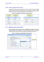
Page 373: ...uipment Providers NEPs and System Integrators SIs the ability to offer customers rapid time to market and inclusive cost effective management of next generation networks The standards compliant EMS uses distributed SNMP based management software optimized to support day to day Network Operation Center NOC activities offering a feature rich management framework It supports fault management configur...

Page 374: ...igure above displays a graphical representation of the device s chassis 5 2 Adding the Device in EMS Once you have defined the IPSec communication protocol for communicating between EMS and the device and configured the device s IP address refer to the Installation Manual you can add the device in the EMS Adding the device to the EMS includes the following main stages a Adding a Region b Defining ...

Page 375: ...and running by performing a ping to its IP address 5 Add the device to the Region by performing the following a Right click the added Region icon and then from the shortcut menu choose Add MG the MG Information dialog box appears Figure 5 4 Defining the IP Address b Enter an arbitrary name for the device and then in the IP Address field enter the device s IP address c Click OK the device is added ...

Page 376: ...nfiguring ISDN NFAS on page 377 5 3 1 General Trunk Configuration This section describes how to provision a PSTN trunk To provision a trunk 1 In the Navigation pane select VoIP PSTN DS1 Trunks the DS1 Trunks List appears Figure 5 5 DS1 Trunks List Table 2 Select a trunk and then in the Navigation pane click VoIP PSTN Trunks Channels the Trunks Channels Table appears in the Main pane Figure 5 6 Tru...

Page 377: ... the PSTN trunks Notes When changing Protocol Type from None to any other protocol reset the device You re not required to reset the device when making subsequent changes to Protocol Type Most Trunk provisioning parameters require that a Trunk Lock Unlock be performed before after configuring them When performing a Lock action all active calls are dropped and users cannot make new calls This is Tr...

Page 378: ...d then in the Configuration pane click Trunk SIP Frame the Trunk SIP Provisioning screen is displayed with the General Settings tab selected 3 Select the ISDN Settings tab the ISDN Settings screen appears Figure 5 8 EMS ISDN Settings Screen 4 Perform the following configurations a Configure each trunk in the group with the same values for the Termination Side parameter b Select the EXPLICIT INTERF...

Page 379: ...the initial Offline configuration but the sequence of configuring or locking the trunks is important To configure ISDN NFAS Trunks on the fly Unlocking an NFAS Group a If there is a Backup trunk for this group it must be unlocked first b The Primary trunk must be unlocked before unlocking any NFAS trunks c NFAS trunks should then be unlocked Locking and Removing an NFAS Group a Lock all NFAS trunk...

Page 380: ... a Click the button to add a new Coder entry and then click Yes to confirm b Double click each field to enter values c Right click the new entry and then choose Unlock Rows 3 Select the Proxy Server tab a Set Proxy Used to Yes b Optional In the Proxy Name field enter the Proxy s name The Proxy name replaces the Proxy IP address in all SIP messages This means that messages are still sent to the phy...

Page 381: ... confirm the Phones screen is displayed b Double click each field to enter values c Right click the new entry and then select Unlock Rows d Click Apply and close the active window Note For T1 ISDN spans configure 1 23 and not 1 24 for B channels Channel 24 is a signaling ISDN channel 6 If a Proxy Server is not implemented map outgoing telephone calls to IP addresses Open the SIP Routing frame Conf...

Page 382: ...appears 2 Select the Authentication Security tab the Authentication Security screen appears Figure 5 10 Authentication Security Screen 3 From the SRTP Offered Suites SRTPofferedSuites drop down list select the required crypto suites 5 6 Provisioning SIP MLPP Parameters This section describes how to configure the MLPP Multi Level Precedence and Preemption parameters using the EMS To configure the M...

Page 383: ...ediaDiffserv global gateway parameter or by using IP Profiles MLPPRoutineRTPDSCP MLPPPriorityRTPDSCP MLPPImmediateRTPDSCP MLPPFlashRTPDSCP MLPPFlashOverRTPDSCP MLPPFlashOverOverRTPDSCP MLPPNormalizedServiceDomain 5 7 Configuring the Device to Operate with SNMPv3 This section describes the SNMPv3 configuration process Configuring SNMPv3 using SSH Configuring SNMPv3 using EMS non configured SNMPv3 S...

Page 384: ...Enter data below Type a period on an empty line to finish The configuration session is now active and all data entered at the terminal is parsed as configuration text formatted as an ini file 4 Type the following text at the configuration session SNMPUsers FORMAT SNMPUsers_Index SNMPUsers_Username SNMPUsers_AuthProtocol SNMPUsers_PrivProtocol SNMPUsers_AuthKey SNMPUsers_PrivKey SNMPUsers_Group SNM...

Page 385: ... which the device belongs and then right click the device 2 From the shortcut menu choose Details the MG Information screen appears Figure 5 12 MG Information Screen 3 Select the SNMPv3 option configure the SNMP fields and then click OK 4 Open the SNMPv3 Users screen Navigation pane System Management SNMP Frame SNMPv3 Users tab 5 From the SNMPv3 Users tab s drop down list choose Unit value the SNM...

Page 386: ...rtcut menu point to Configuration and then click SNMP Configuration the SNMP Configuration window appears Figure 5 13 SNMP Configuration Screen 3 Select the SNMPv3 option 4 Configure the SNMPv3 fields and then select the Update Media Gateway SNMP Settings check box 5 Click OK the update progress is displayed 6 Click Done when complete 7 Open the SNMPv3 Users screen Navigation pane System Managemen...

Page 387: ...r passwords 5 Select a User permission group 6 If the new user wishes to receive traps to the user defined destination select the Use SNMPv3 User Security Profile for Trap Forwarding option to provision Trap destination IP and Port EMS adds this new user to the SNMP Trap Managers Table It is also possible to define an additional trap destination after a new user is defined 5 8 Resetting the Device...

Page 388: ...ow describes how to upgrade the devices software i e cmp file using the EMS To upgrade the device s cmp file 1 From the Tools menu choose Software Manager the Software Manager screen appears Figure 5 15 Software Manager Screen 2 Click the Add File icon the Add Files dialog box appears Figure 5 16 Add Files Screen ...

Page 389: ...f the cmp file d From the Select Product drop down list select the type of device e From the Select Protocol drop down list select the control protocol i e SIP 4 Click OK 5 In the MG Tree select the device that you want to upgrade 6 On the Actions bar click the Software Upgrade button the Files Manager screen appears Figure 5 17 Files Manager Screen 7 Select the file that you want to download to t...

Page 390: ...SIP User s Manual 390 Document LTRT 12804 Mediant 800 MSBG Reader s Notes ...
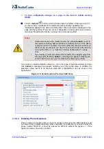
Page 391: ... 232 port refer to the Installation Manual to COM1 or COM2 communication port on your PC b Establish serial communication with the device using a serial communication program such as HyperTerminalTM with the following communication port settings Baud Rate 115 200 bps Data Bits 8 Parity None Stop Bits 1 Flow Control None 2 At the initial CLI prompt type the username default is Admin and then press ...

Page 392: ...ge 344 The only settings that are not restored to default are the management OAMP LAN IP address and the Web interface s login user name and password The loaded ini file must be empty i e contain no parameters or include only comment signs i e semicolons preceding lines parameters The default values assigned to the parameters are according to the cmp file running on the device 6 3 Restoring Defaul...

Page 393: ... CPT and Distinctive Ringing applicable to analog interfaces auxiliary file is comprised of two sections The first section contains the definitions of the Call Progress Tones levels and frequencies that are detected generated by the device The second section contains the characteristics of the Distinctive Ringing signals that are generated by the device see Distinctive Ringing on page 396 You can ...

Page 394: ... second dial tone s definition lines to the first tone definition in the ini file The device reports dial tone detection if either of the two tones is detected The Call Progress Tones section of the ini file comprises the following segments NUMBER OF CALL PROGRESS TONES Contains the following key Number of Call Progress Tones defining the number of Call Progress Tones that are defined in the file ...

Page 395: ...units for the second cadence on off cycle Can be omitted if there isn t a second cadence Third Signal On Time 10 msec Signal On period in 10 msec units for the third cadence on off cycle Can be omitted if there isn t a third cadence Third Signal Off Time 10 msec Signal Off period in 10 msec units for the third cadence on off cycle Can be omitted if there isn t a third cadence Fourth Signal On Time...

Page 396: ... the ringing pattern cadences is specified by the following parameters Burst Ring On Time Configures the cadence to be a burst cadence in the entire ringing pattern The burst relates to On time and the Off time of the same cadence It must appear between First Second Third Fourth string and the Ring On Off Time This cadence rings once during the ringing pattern Otherwise the cadence is interpreted ...

Page 397: ...lert Info header in the INVITE message For example Alert Info Bellcore dr2 or Alert Info http Bellcore dr2 dr2 defines ringing pattern 2 If the Alert Info header is missing the default ringing tone 0 is played An example of a ringing burst definition is shown below Three ringing bursts followed by repeated ringing of 1 sec on and 3 sec off NUMBER OF DISTINCTIVE RINGING PATTERNS Number of Ringing P...

Page 398: ...s to source and or destination number prefixes per FXS endpoint s Typically the Ringing and or Call Waiting tone played is indicated in the SIP Alert info header field of the received INVITE message If this header is not present in the received INVITE then this feature is used and the tone played is according to the settings in this table For example to configure Distinctive Ringing and Call Waiti...

Page 399: ...The raw data files must be recorded with the following characteristics Coders G 711 A law or G 711 µ law Rate 8 kHz Resolution 8 bit Channels mono Once created the PRT file can then be loaded to the device using the Web interface see Loading Auxiliary Files on page 337 The prerecorded tones are played repeatedly This allows you to record only part of the tone and then play the tone for the full du...

Page 400: ...al Plan prefix tags For a detailed description see Dial Plan Prefix Tags for IP to Tel Routing on page 418 The Dial Plan file is first created using a text based editor such as Notepad and saved with the file extension ini This ini file is then converted to a binary file dat using the DConvert utility refer to the Product Reference Manual Once converted it can then be loaded to the device using th...

Page 401: ...llular VoIP area codes 052 054 and 050 In these area codes phone numbers have 8 digits 052 8 054 8 050 8 Defines International prefixes 00 012 014 The number following these prefixes may be 7 to 14 digits in length 00 7 14 012 7 14 014 7 14 Defines emergency number 911 No additional digits are expected 911 0 PLAN2 Defines area codes 02 03 04 In these area codes phone numbers have 7 digits 0 2 4 7 ...

Page 402: ...ine includes five items separated with commas The items are described in the table below Table 7 1 User Information Items Item Description Maximum Size Characters PBX extension The relevant PBX extension number 10 Global phone The relevant global phone number 20 Display name A string that represents the PBX extensions for the Caller ID 30 Username A string that represents the user name for SIP reg...

Page 403: ...ionMode is set to Per Endpoint using the Global phone number in the From To headers The REGISTER messages are sent gradually Initially the device sends requests according to the maximum number of allowed SIP dialogs configured by the parameter NumberOfActiveDialogs After each received response the subsequent request is sent Therefore no more than NumberOfActiveDialogs dialogs are active simultaneo...

Page 404: ...SIP User s Manual 404 Document LTRT 12804 Mediant 800 MSBG Reader s Notes ...
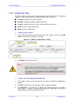
Page 405: ...in the SIP Media Realm table see Media Realms on page 406 and then later assigned to an SRD in the SRD table SIP Interface A SIP signaling interface is a combination of UDP TCP and TLS ports associated with a specific IP address network interface configured in the Multiple Interface table SIP Interfaces are defined n the SIP Signaling Interface table see SIP Interfaces on page 406 where they are a...

Page 406: ... SIP Interfaces per Application within SRD 8 1 1 1 Media Realms A Media Realm is a range of UDP ports that is associated with a media IP interface IP address defined in the Multiple Interface table Media Realms allow you to divide a media RTP traffic IP interface into several realms where each realm is specified by a UDP port range The pool of media interfaces i e Media Realms are defined in the S...

Page 407: ...allowed per SRD An SRD can be associated with many SIP interfaces which are based on one Layer 3 interface with different ports Separating signaling traffic of different customers to use different routing tables manipulations SIP definitions etc The figure below illustrates the SBC call flow between an enterprises LAN IP PBX and an ITSP WAN implementing different interfaces IP addresses and ports ...

Page 408: ...iple SIP signaling and RTP interfaces In this example the device serves as the interface between the enterprise s PBX connected using an E1 T1 trunk and two ITSP s as shown in the figure below Figure 8 4 Multiple SIP Signaling RTP Interfaces Example Note that only the steps specific to multiple SIP signaling RTP configuration are described in detail in the procedure below ...

Page 409: ...Figure 8 5 Defining a Trunk Group for PSTN 2 Configure the Trunk in the Trunk Settings page Configuration tab VoIP menu GW and IP to IP submenu Hunt Group Hunt Group Settings 3 Configure the IP interfaces in the Multiple Interface Table page Configuration tab VoIP menu Network submenu IP Settings Figure 8 6 Defining IP Interfaces 4 Configure SIP Media Realms in the SIP Media Realm Table page Confi...

Page 410: ...efining SRDs 6 Configure the SIP Interfaces in the SIP Interface Table page Configuration tab VoIP menu Control Network submenu SIP Interface Table Figure 8 9 Defining SIP Interfaces 7 Configure Proxy Sets in the Proxy Sets Table page Configuration tab VoIP menu Control Network submenu Proxy Sets Table The figure below configures ITSP A Do the same for ITSP B but for Proxy Set 2 with IP address 21...

Page 411: ...1 and Media Realm to Realm2 Figure 8 11 Defining IP Groups 9 Configure IP to Trunk Group routing in the Inbound IP Routing Table page Configuration tab VoIP menu GW and IP to IP submenu Routing submenu IP to Trunk Group Routing Figure 8 12 Defining IP to Trunk Group Routing 10 Configure Trunk Group to IP routing in the Outbound IP Routing Table page Configuration tab VoIP menu GW and IP to IP subm...

Page 412: ...ames from the buffer at regular intervals in order to produce continuous speech As long as delays in the network do not change jitter by more than 10 msec from one packet to the next there is always a sample in the buffer for the coder to use If there is more than 10 msec of delay at any time during the call the packet arrives too late The coder tries to access a frame and is not able to find one ...

Page 413: ...phone numbers and SIP URI user names in the routing and manipulation tables Table 8 1 Dialing Plan Notations Notation Description Example n m Represents a range of numbers Note Range of letters is not supported 5551200 5551300 represents all numbers from 5551200 to 5551300 123 100 200 represents all numbers from 123100 to 123200 n m Represents multiple numbers Up to three digits can be used to den...

Page 414: ...meout expires e g for open numbering schemes This is defined using the TimeBetweenDigits parameter This is the time that the device waits between each received digit When this inter digit timeout expires the device uses the collected digits to dial the called destination number The phone s pound key is pressed Digit string i e dialed number matches one of the patterns defined in the digit map Digi...

Page 415: ...e Digit Map can be used to define digit patterns MaxDigits parameter that are shorter than those defined in the Dial Plan or left at default For example xx T Digit Map instructs the device to use the Dial Plan and if no matching digit pattern it waits for two more digits and then after a timeout TimeBetweenDigits parameter it sends the collected digits Therefore this ensures that calls are not rej...

Page 416: ...ot found then attempts to locate a matching digit pattern in the Digit Map configured by the DigitMapping parameter It may be useful to configure both Dial Plan file and Digit Maps For example the Digit Map can be used for complex digit patterns which are not supported by the Dial Plan and the Dial Plan can be used for long lists of relatively simple digit patterns In addition as timeout between d...

Page 417: ...343434181 056788118 2 4 0 04343434181 If we take the first Dial Plan rule in the example above i e 0567811181 0 04343434181 the received Calling Number Party of 0567811181 is changed to 04343434181 and sent to the IP with a SIP INVITE as follows Via SIP 2 0 UDP 211 192 160 214 5060 branch z9hG4bK3157667347 From sip 04343434181 kt co kr 5060 tag de0004b1 To sip 01066557573 kt co kr 5060 Call ID 585...

Page 418: ...n text Dial string prefix ranges can be defined in brackets User defined routing tag text Note Dial Plan Prefix Tags are not applicable to FXS and FXO interfaces The example configuration below assumes a scenario where multiple prefixes exist for local and long distance calls To use Dial Plan file routing tags 1 Load an ini file to the device that selects the Dial Plan index e g 1 for routing tags...

Page 419: ...gits From Left field is set to 4 The Destination Prefix field is set to the value LONG and the Stripped Digits From Left field is set to 4 Figure 8 15 Configuring Manipulation for Removing Label 8 3 2 Manipulating Number Prefix The device supports a notation for adding a prefix where part of the prefix is first extracted from a user defined location in the original destination or source number Thi...

Page 420: ... example 2 the first seven digits from the left are removed from the original number in the example the number is changed to 8888888 3 the prefix that was previously calculated is then added 8 3 3 Emergency Phone Number Services E911 The device supports emergency phone number services The device supports the North American emergency telephone number system known as Enhanced 911 E911 according to t...

Page 421: ...s in the SIP From header as one string 5 The FXS device generates a mid call wink signal two subsequent polarity reversals toward the E911 tandem switch upon either detection of an RFC 2833 hookflash telephony event or if a SIP INFO message with a hooflash body is received from the PSAP see the example below The duration of this flashhook wink signal is configured using the parameter FlashHookPeri...

Page 422: ... after it detects the line seizure EnableTransfer 1 for call transfer LineTransferMode 1 for call transfer WaitforDialTime 1000 for call transfer SwapTEl2IPCalled CallingNumbers 1 DTMFDetectorEnable 0 MFR1DetectorEnable 1 DelayBeforeDIDWink 200 for 200 msec can be configured in the range from 0 default to 1000 Note Modification of the WinkTime and FlashHookPeriod parameters require a device reset ...

Page 423: ...ws for KP for ST B for STP For example if ANI and PANI are received the SIP INVITE contains the following From header From sip nnnnnnnnnnnn mmmmmmmmmm 10 2 3 4 tag 1c14 Note It is possible to remove the and characters using the device s number manipulation rules If the device receives the SIP INFO message below it then generates a hookflash mid call Wink signal INFO sip 4505656002 192 168 13 40 50...

Page 424: ...ials 911 the device receives the SIP INVITE message and makes a call to the PSAP as follows 1 The FXO device seizes the line 2 PSAP sends a Wink signal 250 msec to the device 3 Upon receipt of the Wink signal the device dials MF digits after a user defined time WaitForDialTime containing the caller s ID ANI obtained from the SIP headers From or P Asserted Identity 4 When the PSAP operator answers ...

Page 425: ...k sent by the PSAP for starting the device s dialing 500 msec wink during the call IsTwoStageDial 0 EnableHold 0 EnableTransfer 0 Use RFC 2833 DTMF relay RxDTMFOption 3 TxDTMFOption 4 RFC2833PayloadType 101 TimeToSampleAnalogLineVoltage 100 WaitForDialTime 1000 default is 1 sec The device expects to receive the ANI number in the From and or P Asserted Identity SIP header If the pseudo ANI number e...

Page 426: ...etected To overcome this problem configure the parameter TimeToSampleAnalogLineVoltage to 100 instead of 1000 msec which is the default value The wink is then detected only after this timeout 50 msec minimum 150 msec Below are two examples for a INVITE messages and b INFO messages generated by hook flash Example a INVITE message with ANI 333333444444 and pseudo ANI 0123456789 INVITE sip 301 10 33 ...

Page 427: ...taining to the same Hunt Group for which the E911 call was initially destined and if the channel select mode configured by the ChannelSelectMode parameter is set to other than By Dest Number 0 The preemption is done only if the incoming IP to Tel call is identified as an emergency call The device identifies emergency calls by one of the following The destination number of the IP call matches one o...

Page 428: ...TMFOption 2 Note that in this mode DTMF digits are erased from the audio stream DTMFTransportType is automatically set to 0 Using RFC 2833 relay with Payload type negotiation DTMF digits are carried to the remote side as part of the RTP stream in accordance with RFC 2833 standard To enable this mode define the following RxDTMFOption 3 TxDTMFOption 4 Note that to set the RFC 2833 payload type with ...

Page 429: ...ortType is automatically set to 0 Notes The device is always ready to receive DTMF packets over IP in all possible transport modes INFO messages NOTIFY and RFC 2833 in proper payload type or as part of the audio stream To exclude RFC 2833 Telephony event parameter from the device s SDP set RxDTMFOption to 0 in the ini file The following parameters affect the way the device handles the DTMF digits ...

Page 430: ...arkets The digital design of the filters and gain stages also ensures high reliability no drifts over temperature or time and simple variations between different line types The FXS Coefficient types provide best termination and transmission quality adaptation for two FXS line type interfaces This parameter affects the following AC and DC interface parameters DC battery feed characteristics AC impe...

Page 431: ... the IP caller doesn t dial the PSTN number upon hearing a dial tone Figure 8 19 Call Flow for One Stage Dialing One stage dialing incorporates the following FXO functionality Waiting for Dial Tone Enables the device to dial the digits to the Tel side only after detecting a dial tone from the PBX line The ini file parameter IsWaitForDialTone is used to configure this operation Time to Wait Before ...

Page 432: ...ling is when the IP caller is required to dial twice The caller initially dials to the FXO device and only after receiving a dial tone from the PBX via the FXO device dials the destination telephone number Figure 8 20 Call Flow for Two Stage Dialing Two stage dialing implements the Dialing Time feature Dialing Time allows you to define the time that each digit can be separately dialed By default t...

Page 433: ...ent from the other end before sending digits This serves as an integrity check that identifies a malfunctioning trunk and allows the network to send a re order tone to the calling party The start dial signal is a wink from the PBX to the FXO device The FXO then sends the last four to five DTMF digits of the called number The PBX uses these digits to complete the routing directly to an internal sta...

Page 434: ...able TargetOfChannel see Analog Telephony Parameters or the embedded Web server s Automatic Dialing screen see Automatic Dialing on page 184 The SIP call flow diagram below illustrates Automatic Dialing Figure 8 21 Call Flow for Automatic Dialing 8 3 5 2 2 2 Collecting Digits Mode When automatic dialing is not defined the device collects the digits ...

Page 435: ... generate a dial tone that is sent to the IP and the IP side may dial digits of a new destination Blind Transfer to the Tel side A blind transfer is one in which the transferring phone connects the caller to a destination line before ringback begins The ini file parameter LineTransferMode must be set to 1 The blind transfer call process is as follows FXO receives a REFER request from the IP side F...

Page 436: ...etected on the Tel side assuming the PBX CO generates this tone This method requires the correct tone frequencies and cadence to be defined in the Call Progress Tones file If these frequencies are not known define them in the CPT file the tone produced by the PBX CO must be recorded and its frequencies analyzed refer to Adding a Reorder Tone to the CPT File in the Reference Manual This method is s...

Page 437: ... of Ring Detection Timeout depends on the following Automatic dialing is disabled and Caller ID is enabled if the second ring signal is not received for a user defined time using the parameter FXOBetweenRingTime the FXO device doesn t initiate a call to the IP Automatic dialing is enabled if the remote party doesn t answer the call and the ringing signal stops for a user defined time using the par...

Page 438: ...ion i e phone connected to the FXS interface To make a call from the FXS interface 1 Off hook the phone and wait for the dial tone from the PBX This is as if the phone is connected directly to the PBX The FXS and FXO interfaces establish a voice path connection from the phone to the PBX immediately after the phone is off hooked 2 Dial the destination number e g phone number 201 The DTMF digits are...

Page 439: ... Each PBX line is routed to the same phone connected to the FXS device The call disconnects when the phone connected to the FXS device is on hooked 8 3 5 3 3 Message Waiting Indication for Remote Extensions The device supports the relaying of Message Waiting Indications MWI for remote extensions and voice mail applications Instead of subscribing to an MWI server to receive notifications of pending...

Page 440: ...le between calls using the Hook Flash button Figure 8 25 Call Waiting for Remote Extensions 8 3 5 3 5 FXS Gateway Configuration The procedure below describes how to configure the FXS interface at the remote PBX extension To configure the FXS interface 1 In the Hunt Group Table page see assign the phone numbers 100 to 104 to the device s endpoints Figure 8 26 Assigning Phone Numbers to FXS Endpoint...

Page 441: ... which the PBX is directly connected To configure the FXO interface 1 In the Hunt Group Table page see assign the phone numbers 200 to 204 to the device s FXO endpoints Figure 8 29 Assigning Phone Numbers to FXO Ports 2 In the Automatic Dialing page enter the phone numbers of the FXS device in the Destination Phone Number fields When a ringing signal is detected at Port 1 the FXO device automatica...

Page 442: ...or if the original call fails and the device has made two additional attempts to establish the call without success an alternative route is searched in the table and used for routing the call 8 3 6 2 Determining the Availability of Destination IP Addresses To determine the availability of each destination IP address or host name in the routing table one or all of the following user defined methods...

Page 443: ...o match is achieved for any of the transport capabilities fallback to existing logic occurs according to the parameter IsFaxUsed 8 3 7 2 Fax Modem Transport Modes The device supports the following transport modes for fax per modem type V 22 V 23 Bell V 32 V 34 T 38 fax relay see T 38 Fax Relay Mode on page 444 G 711 Transport switching to G 711 when fax modem is detected see G 711 Fax Modem Transp...

Page 444: ...hen working with other T 38 decoders 8 3 7 2 1 1 Switching to T 38 Mode using SIP Re INVITE In the Switching to T 38 Mode using SIP Re INVITE mode upon detection of a fax signal the terminating device negotiates T 38 capabilities using a Re INVITE message If the far end device doesn t support T 38 the fax fails In this mode the parameter FaxTransportMode is ignored To configure T 38 mode using SIP...

Page 445: ...ho canceller the echo canceller is disabled only on modem transmission A gpmd attribute is added to the SDP according to the following format For G 711A law a gpmd 0 vbd yes ecan on or off for modems For G 711 µ law a gpmd 8 vbd yes ecan on or off for modems The parameters FaxTransportMode and VxxModemTransportType are ignored and automatically set to the mode called transparent with events To con...

Page 446: ... during the bypass period are regular voice RTP packets per the selected bypass coder but with a different RTP payload type according to the parameters FaxBypassPayloadType and ModemBypassPayloadType During the bypass period the coder uses the packing factor which is defined by the parameter FaxModemBypassM The packing factor determines the number of coder payloads each the size of FaxModemBypassB...

Page 447: ...ts using NSEpayloadType usually 100 These packets signal the remote device to switch to G 711 coder according to the parameter FaxModemBypassCoderType After a few NSE packets are exchanged between the devices both devices start using G 711 packets with standard payload type 8 for G 711 A Law and 0 for G 711 Mu Law In this mode no Re INVITE messages are sent The voice channel is optimized for fax m...

Page 448: ...rtType 3 BellModemTransportType 3 8 3 7 2 7 Fax Modem Transparent Mode In this mode fax and modem signals are transferred using the current voice coder without notifications to the user and without automatic adaptations It s possible to use the Profiles mechanism see Coders and Profile Definitions on page 138 to apply certain adaptations to the channel used for fax modem e g to use the coder G 711...

Page 449: ... IsFaxUsed 0 or 3 FaxTransportType 2 FaxModemNTEMode 1 VxxModemTransportType 2 8 3 7 3 V 34 Fax Support V 34 fax machines can transmit data over IP to the remote side using various methods The device supports the following modes for transporting V 34 fax data over IP Bypass mechanism for V 34 fax transmission see Bypass Mechanism for V 34 Fax Transmission on page 449 T38 Version 0 relay mode i e f...

Page 450: ...parent V32ModemTransportType 0 V23ModemTransportType 0 V22ModemTransportType 0 8 3 7 3 3 V 34 Fax Relay for SG3 Fax Machines Super Group 3 SG3 is a standard for fax machines that support speeds of up to 33 6 kbps through V 34 half duplex HD modulation This section describes how to configure the device to support V 34 SG3 fax relay based on the ITU Specification T 38 version 3 To enable the device ...

Page 451: ...are not supported For example the device sends or receives the following INVITE message negotiating both audio and image media INVITE sip 2001 10 8 211 250 user phone SIP 2 0 Via SIP 2 0 UDP 10 8 6 55 branch z9hG4bKac1938966220 Max Forwards 70 From sip 318 10 8 6 55 tag 1c1938956155 To sip 2001 10 8 211 250 user phone Call ID 193895529241200022331 10 8 6 55 CSeq 1 INVITE Contact sip 318 10 8 6 55 ...

Page 452: ...nd associated RTP payload types gpmd SDP attribute supported codecs and packetization periods for all codec payload types ptime SDP attribute After this initial negotiation no Re INVITE messages are necessary as both endpoints are synchronized in terms of the other side s capabilities If negotiation fails i e no match was achieved for any of the transport capabilities fallback to existing logic oc...

Page 453: ...he specific supplementary service that is used When working with certain application servers such as BroadSoft s BroadWorks in client server mode the application server controls all supplementary services and keypad features by itself the device s supplementary services must be disabled 8 3 8 1 Call Hold and Retrieve Initiating Call Hold and Retrieve Active calls can be put on hold by pressing the...

Page 454: ...ess 0 0 0 0 or the inactive string in SDP the device stops sending RTP and plays a local Held tone When an active call receives a Re INVITE message with the sendonly string in SDP the device stops sending RTP and listens to the remote party In this mode it is expected that on hold music or any other hold tone is played over IP by the remote party You can also configure the device to keep a call on...

Page 455: ...he phone and then on hooking the handset To resume the call the phone user typically presses the same keys or button again and then off hooks the phone During the suspended state the device plays a Howler tone to the remote party This service is also supported when instead of pressing the call park button s the phone cable is disconnected suspending the call and then reconnected again resuming the...

Page 456: ... can receive and act upon receiving INVITE with REPLACES in which case the old call is replaced by the new one The INVITE with REPLACES can be used to implement Directed Call Pickup 8 3 8 4 1 Consultation Call Transfer The device supports Consultation Call Transfer using the SIP REFER message and Replaces header The common method to perform a consultation transfer is described in the following exa...

Page 457: ...all between B and C similar to consultation transfer but skipping the consultation stage Note Currently the device does not support blind transfer for BRI interfaces 8 3 8 5 Call Forward For digital interfaces The device supports Call Deflection ETS 300 207 1 for Euro ISDN and QSIG ETSI TS 102 393 for Network and User sides which provides IP ISDN interworking of call forwarding call diversion when...

Page 458: ...sponses for redirecting calls with a new contact 8 3 8 5 1 Call Forward Reminder Ring The device supports the Call Forward Reminder Ring feature for FXS interfaces whereby the device s FXS endpoint emits a short ring burst only if in onhook state when a third party Application Server e g softswitch forwards an incoming call to another destination This is important in that it notifies audibly the F...

Page 459: ...r the special dial tone for Call Forward For playing the special dial tone the received SIP NOTIFY message must contain the following headers From and To contain the same information indicating the specific endpoint Event ua profile Content Type application simservs xml Message body is the XML body and contains the dial tone pattern set to special condition tone ss dial tone pattern special condit...

Page 460: ...rd 72 to extension number 100 This code is defined using the SuppServCodeCFU parameter INVITE sip 72100 10 33 8 53 user phone SIP 2 0 Via SIP 2 0 UDP 10 33 2 5 5060 branch z9hG4bKWDSUKUHWFEXQSVOUVJGM From sip 400 10 33 2 5 user phone tag DUOROSXSOYJJLNBFRQTG To sip 72100 10 33 8 53 user phone Call ID GMNOVQRRXUUCYCQSFAHS 10 33 2 5 CSeq 1 INVITE Contact sip 400 10 33 2 5 5060 Supported em 100rel ti...

Page 461: ...ting when a 182 Call Queued response is received Note The Call Waiting feature is applicable only to FXS FXO interfaces 8 3 8 7 Message Waiting Indication The device supports Message Waiting Indication MWI according to IETF Internet Draft draft ietf sipping mwi 04 including SUBSCRIBE to MWI server Note For a detailed description on IP voice mail configuration refer to the IP Voice Mail CPE Configu...

Page 462: ...request from a softswitch is as follows 1 The softswitch sends a SIP SUBSCRIBE message to the device 2 The device responds by sending an empty SIP NOTIFY to the softswitch and then sending an ISDN Setup message with Facility IE containing an MWI Interrogation request to the PBX 3 The PBX responds by sending to the device an ISDN Connect message containing Facility IE with an MWI Interrogation resu...

Page 463: ... standard using the parameter ETSICallerIDTypeOneSubStandard Enable or disable per port the caller ID generation for FXS and detection for FXO using the Generate Detect Caller ID to Tel table EnableCallerID If a port isn t configured its caller ID generation detection are determined according to the global parameter EnableCallerID EnableCallerIDTypeTwo disables enables the generation of Caller ID ...

Page 464: ...of the PBX instead of to the device s FXO interface and verify that it displays the caller ID If the above does not solve the problem you need to record the caller ID signal and send it to AudioCodes as described below To record the caller ID signal using the debug recording mechanism 1 Access the FAE page by appending FAE to the device s IP address in the Web browser s URL for example http 10 13 ...

Page 465: ...he Caller ID Name field the caller ID is restricted and the value in the Presentation field is ignored The value of the Presentation field that is defined in the Caller Display Information table can be overridden by configuring the Presentation parameter in the Tel to IP Source Number Manipulation table Therefore this table can be used to set the presentation for specific calls according to Source...

Page 466: ...in the REFER messages that are sent to the two remote parties For this mode the 3WayConferenceMode parameter is set to 0 default Conferencing controlled by an external third party Conference media server The Conference initiating INVITE sent by the device uses only the ConferenceID as the Request URI The Conference server sets the Contact header of the 200 OK response to the actual unique identifi...

Page 467: ...sed if the incoming SIP INVITE or PRI Setup message contains an invalid priority or Precedence Level value respectively For each MLPP call priority level the Multiple Differentiated Services Code Points DSCP can be set to a value from 0 to 63 Table 8 5 MLPP Call Priority Levels Precedence and DSCP Configuration Parameters MLPP Precedence Level Precedence Level in Resource Priority SIP Header DSCP ...

Page 468: ...all is being preempted by another call CANCEL If an outgoing call is being preempted by another call 480 Temporarily Unavailable 486 User Busy 488 Not Acceptable Here Due to incoming calls being preempted by another call The device receives SIP requests with preemption reason cause 5 in the following cases The softswitch performs a network preemption of an active call the following sequence of eve...

Page 469: ...w F1 INVITE 10 8 201 108 10 8 201 161 INVITE sip 2000 10 8 201 161 user phone SIP 2 0 Via SIP 2 0 UDP 10 8 201 108 branch z9hG4bKacsiJkDGd From sip 6000 10 8 201 108 tag 1c5354 To sip 2000 10 8 201 161 Call ID 534366556655skKw 6000 2000 10 8 201 108 CSeq 18153 INVITE Contact sip 8000 10 8 201 108 user phone User Agent Audiocodes Sip Gateway Mediant 800 MSBG v 6 00 010 006 Supported 100rel em Allow...

Page 470: ...000 10 8 201 108 Server Audiocodes Sip Gateway Mediant 800 MSBG v 6 00 010 006 CSeq 18153 INVITE Supported 100rel em Content Length 0 Note Phone 2000 answers the call and then sends a 200 OK message to device 10 8 201 108 F4 200 OK 10 8 201 161 10 8 201 108 SIP 2 0 200 OK Via SIP 2 0 UDP 10 8 201 108 branch z9hG4bKacsiJkDGd From sip 6000 10 8 201 108 tag 1c5354 To sip 2000 10 8 201 161 tag 1c7345 ...

Page 471: ...OK 200 10 8 201 10 10 8 201 108 SIP 2 0 200 OK Via SIP 2 0 UDP 10 8 201 108 branch z9hG4bKacRKCVBud From sip 6000 10 8 201 108 tag 1c5354 To sip 2000 10 8 201 161 tag 1c7345 Call ID 534366556655skKw 6000 2000 10 8 201 108 Server Audiocodes Sip Gateway Mediant 800 MSBG v 6 00 010 006 CSeq 18154 BYE Supported 100rel em Content Length 0 8 3 9 2 SIP Authentication Example The device supports basic and...

Page 472: ...15 33 54 GMT Server Columbia SIP Server 1 17 Content Length 0 WWW Authenticate Digest realm audiocodes com nonce 11432d6bce58ddf02e3b5e1c77c010d2 stale FALSE algorithm MD5 3 According to the sub header present in the WWW Authenticate header the correct REGISTER request is created 4 Since the algorithm is MD5 The username is equal to the endpoint phone number 122 The realm return by the proxy is au...

Page 473: ...654982194 10 1 1 200 Server Audiocodes Sip Gateway Mediant 800 MSBG v 6 00 010 006 CSeq 1 REGISTER Contact sip 122 10 1 1 200 Expires 3600 Authorization Digest username 122 realm audiocodes com nonce 11432d6bce58ddf02e3b5e1c77c010d2 uri 10 2 2 222 response b9c45d0234a5abf5ddf5c704029b38cf 7 Upon receiving this request and if accepted by the Proxy the proxy returns a 200 OK response closing the REG...

Page 474: ...e assign the phone numbers 101 to 104 to the device s endpoints Figure 8 35 Assigning Phone Numbers to Device 10 2 37 10 2 For the second device 10 2 37 20 in the Hunt Group Table page assign the phone numbers 201 to 204 to the device s endpoints Figure 8 36 Assigning Phone Numbers to Device 10 2 37 20 3 Configure the following settings for both devices In the Outbound IP Routing Table page see Co...

Page 475: ... ITSPs By implementing the device s enhanced and flexible routing capabilities you can design complex routing schemes This section provides an example of an elaborate routing scheme for SIP trunking between an Enterprise s PBX and two Internet Telephony Service Providers ITSP using the device Scenario In this example an Enterprise has deployed the device with FXS interfaces The first four phones o...

Page 476: ...Sets and for each enable Proxy Keep Alive using SIP OPTIONS and round robin load balancing method Proxy Set 1 includes two IP addresses of the first ITSP ITSP 1 10 33 37 77 and 10 33 37 79 and using UDP Proxy Set 2 includes two IP addresses of the second ITSP ITSP 2 10 8 8 40 and 10 8 8 10 and using TCP The figure below displays the configuration of Proxy Set ID 1 Perform similar configuration for...

Page 477: ...en the local PSTN and the device Hunt Group ID 2 Figure 8 41 Assigning Channels to Hunt Groups 5 In the Hunt Group Settings page configure Per Account registration for Hunt Group ID 1 without serving IP Group and associate it with IP Group 1 Configure Per Endpoint registration for Hunt Group ID 2 and associated it with IP Group 2 Figure 8 42 Configuring Registration Mode for Hunt Groups and Assign...

Page 478: ...PBX This interoperability includes the mapping of PSTN PBX Call Progress Tones to SIP 4xx or 5xx responses for IP to Tel calls The converse is also true for Tel to IP calls the SIP 4xx or 5xx responses are mapped to tones played to the PSTN PBX When establishing an IP to Tel call the following rules are applied If the remote party PSTN PBX is busy and the FXO device detects a Busy tone it sends a ...

Page 479: ... The device sends this information in the SIP X Resources header with the following parameters telchs specifies the total telephone channels as well as the number of free available telephone channels mediachs not applicable Below is an example of the X Resources X Resources telchs 12 4 mediachs 0 0 In the example above telchs specifies the number of available channels and the number of occupied ch...

Page 480: ...nfiguration example see SBC Configuration Example on page 546 8 4 1 Overview The SBC application supports up to 150 SBC sessions and provides the following main features NAT traversal see NAT Traversal on page 481 VoIP firewall and security for signaling and media see VoIP Firewall on page 481 Topology hiding see Topology Hiding on page 481 SIP normalization see SIP Normalization on page 482 Survi...

Page 481: ... in the device s firewall based on Offer Answer SDP negotiations Deep packet inspection of all RTP packets Late rouge detection if a SIP session was gracefully terminated and someone tries to ride on it with rouge traffic from the already terminated RTP and SIP context the VoIP Firewall prevents this from occurring Disconnects call after user defined time if RTP connection is broken Black White li...

Page 482: ... Routing on page 556 8 4 2 SIP Network Definitions The device s SBC application can implement multiple SIP signaling and RTP media interfaces For a detailed description see Multiple SIP Signaling Media Interfaces Environment on page 405 8 4 3 SIP Dialog Initiation Process The device s SIP dialog initiation process concerns all incoming SIP dialog initiation requests This includes SIP methods such ...

Page 483: ...rmining Source and Destination URL The SIP protocol has more than one URL in a dialog establishing request that might represent the source and destination URL When handling an incoming request the device determines which SIP headers are used for source and destination URLs Once these URLs are determined the input user and host are taken from them INVITE dialogs ...

Page 484: ...e classified according to its Proxy Set if in the IP Group table the parameter ClassifyByProxySet is enabled If enabled the device classifies Requests arriving from the IP Group s Proxy Set as coming from this IP Group The classification is done according to the Proxy IP list in case of host names then according to the dynamically resolved IP address list Note that this classification is not relev...

Page 485: ...mprehensive and flexible routing scheme Routing rules according to Layer 3 4 and SIP characteristics Routing to different destination types Request URI of incoming SIP dialog initiating requests Specific destination IP address based on IP address host name port transport type and or SRD Routing to a host name can be resolved using NAPTR SRV A Record Specific FQDN NAPTR SRV A Record Resolutions Reg...

Page 486: ...ce IP Group Source Phone Prefix and or Source Host Prefix For all destination types listed above except destination IP Group the IP Group can optionally be itself configured to provide destination SRD and or IP Profile If neither destination SRD nor destination IP Group are defined the destination SRD is the source SRD and the destination IP Group is its default IP Group Figure 8 49 IP to IP Routi...

Page 487: ...Identity header exists either in the incoming INVITE or added by the device a Privacy header is added with the value id 2 Restrict the user identity is restricted the restricted presentation is as mentioned above 3 Remove Restriction the device attempts to reveal the user identity by setting user values to the From header and removing the privacy id value if the Privacy header exists If the From h...

Page 488: ...ns table MessageManipulations parameter This feature enables the normalization of SIP messaging fields between communicating network segments For example it allows service providers to design their own policies on the SIP messaging fields that must be present before a SIP call enters their network Similarly enterprises and small businesses may have policies for the information that can enter or le...

Page 489: ...rules on the same SIP message Figure 8 52 SIP Header Manipulation Example The manipulation is performed on SIP messages according to the Classification table source destination of username host prefixes and source IP address The manipulation can be performed on message type Method Request Response and Response type Message manipulations are performed only after the classification inbound manipulat...

Page 490: ...Layer 3 network and are associated with the same SRD Typically the device is configured as the user agent s outbound proxy and the device is configured using the IP2IP Routing table to route requests received from this IP Group to the serving proxy and vice versa Survivability can be achieved using the alternative routing feature 8 4 4 1 Initial Registration Request Processing Registration request...

Page 491: ...minated by the device This is configured by the SBCUserRegistrationTime SBCProxyRegistrationTime and SBCSurvivabilityRegistrationTime parameters 9 By default the Contact of the outgoing REGISTER is populated with a unique Contact generated by the device and associated with this specific registration Alternatively the original user can be retained in the Contact and used in the outgoing REGISTER re...

Page 492: ...atch but instead replies with 200 OK used for Survivability Once a match is found the request is routed either to the contact received in the initial registration or if the device identifies that the user agent is behind a NAT to the source IP address of the initial registration 8 4 4 4 Registration Refreshes Registration refreshes are incoming REGISTER requests that are associated with a specific...

Page 493: ...nt management and termination of media sessions within the SIP protocol Media sessions are created using the SIP offer answer mechanism If successful the result is a bi directional media RTP flow e g audio fax modem DTMF Each offer answer may create more than one media session of different types e g audio and fax In a SIP dialog multiple offer answer transactions may occur each may change the medi...

Page 494: ...hat flows through the opened pin holes Adding of media functionality to SIP user agents Transcoding for a description on the transcoding modes see Transcoding Modes on page 499 Broken connection According to the above functionalities the call can be configured to operate in one of the following modes Media Anchoring without Transcoding Transparent RTP traverses the device with minimal RTP packet c...

Page 495: ...en there are no common coders between the two user agents i e the SDP answer from one user agent doesn t include any coder included in the offer previously sent by the other user agent For transcoding the device can be configured to add media capabilities to user agents pertaining to a specific IP Group and then perform transcoding in cases where the selected coder in the answer SDP is not one tha...

Page 496: ...s list has been configured for the user agent s IP Group i e Destination IP Group The incoming offer contains at least one supported coder otherwise transcoding can t be performed Both legs have available DSP s T 38 doesn t appear in the offer If the above prerequisites are not met the SDP offer is sent without the extended coders list The coders from the extended list are added after the ones fro...

Page 497: ...andling the RTP SRTP media flow between remote SIP user agents UA The RTP packet flow does not traverse the device instead the two SIP UA s establish a direct RTP SRTP flow between one another Signaling continues to traverse the device with minimal intermediation and involvement to enable certain SBC abilities such as routing In contrast to the regular SBC implementation the No Media Anchoring fea...

Page 498: ...le follow me service located in the WAN while the other UA is located in the LAN calls between these two UA s can t be established until IntraSRDMediaAnchoring is set to 0 as the device doesn t interfere in the SIP signaling In other words parameters such as IP addresses are not manipulated for calls between LAN and WAN although required When the parameter SBCDirectMedia is disabled No Media Ancho...

Page 499: ...e different media capabilities In the SBC application forced transcoding of voice in an SBC session allows the device to receive capabilities that are not negotiated between the SBC legs For example if one would like to force Gain Control on the SBC session to use voice transcoding even though both sides of the session have negotiated without SBC intervention for example coder extension Note To im...

Page 500: ...d coders b The source first leg may have Allowed Coders i e list of coders that can be used enforced c The device checks for common coders between the SDP offered coders and the Allowed Coders Group list For example assume the following The SDP coder offer includes the following coders G729 G711 and G723 The source first leg includes the following Allowed Coders G711 and G729 The device selects th...

Page 501: ...rtpmap 8 PCMA 8000 a rtpmap 96 telephone event 8000 a fmtp 96 0 15 a ptime 20 a sendrecv a rtpmap 18 G729 8000 a fmtp 18 annexb no In the SDP the m audio 6010 RTP AVP 8 0 96 18 line shows that the coder priority has changed G711A law 8 and then G711U law 0 and that the extended coder G729 18 has been added The G723 coder 4 in the original offer was removed as it was not defined in the Allowed Code...

Page 502: ...s can be applied per SRD and or IP Group and per user identified by its registered contact This is especially important for MSBG applications where VoIP and Data traffic contend on the WAN throughput which may be limited by itself For example DSL WAN access interface is very limited in the uplink Therefore by controlling the number of calls allowed bandwidth can be reserved for Data applications I...

Page 503: ...nt as a result of the 3xx traverse the device This is enabled by the parameter SBC3xxBehavior Reasons for enforcing resultant INVITEs to traverse the SBC may vary The user that receives the 3xx can t route to the 3xx contact i e the user is on the LAN and the new contact is on the WAN In such a scenario the device helps the user reach the WAN contact and overcome NAT problems Enforce certain SBC p...

Page 504: ...ce s URL as host part e g Contact sip Prefix_Key_User SBC 5070 transport udp q 0 5 3 The device sends this manipulated SIP 3xx response to the Far End User FEU 4 The FEU sends a new request with the Request URI set to the value of the received 3xx response s Contact header e g RequestURI sip Prefix_Key_User SBC 5070 transport udp 5 Upon receipt of the new request from the FEU the device replaces t...

Page 505: ...IP Diversion and History Info headers is described in the table below Table 8 6 Handling of SIP Diversion and History Info Headers Parameter Value SIP Header Present in Received SIP Message Diversion History Info Diversion and History Info HistoryInfoMode Add DiversionMode Remove Diversion converted to History Info Diversion removed Not present Diversion removed HistoryInfoMode Remove DiversionMod...

Page 506: ...d Prefix 3 Add suffix 4 Remove Suffix 5 Remove Prefix 6 The maximum length of the value for a manipulation is 299 characters 8 4 9 2 Supported Header Types 8 4 9 2 1 Accept An example of the header is shown below Accept application sdp The header properties as shown in the table below Header Level Action Add Delete Modify List Entries Operations Supported Yes Yes No N A Keyword Sub Types Attribute...

Page 507: ...pt language 0 en il cz it 0 Result Accept Language en il cz it 8 4 9 2 3 Allow An example of the header is shown below Allow REGISTER OPTIONS INVITE ACK CANCEL BYE NOTIFY PRACK REFER INFO SUB SCRIBE The header properties as shown in the table below Header Level Action Add Delete Modify List Entries Operations Supported Yes Yes No N A Keyword Sub Types Attributes N A N A Read Write Below is a heade...

Page 508: ...p abc GIAPOFWRBQKJVAETIODI 10 132 10 128 8 4 9 2 5 Contact An example of the header is shown below Contact sip 555 10 132 10 128 5080 The header properties as shown in the table below Header Level Action Add Delete Modify List Entries Operations Supported No No No 8 Keyword Sub Types Attributes Expires Integer Read Write GruuContact String Read Write IsGRUU Boolean Read Write Name String Read Writ...

Page 509: ...tions 0 1 Invite header cseq num 1 header contact url user 2 fred 0 Result Contact sip fred 10 132 10 128 5070 8 4 9 2 7 Diversion An example of the header is shown below Diversion sip 654 IPG2Host user phone reason user busy screen no privacy off counter 1 The header properties as shown in the table below Header Level Action Add Delete Modify List Entries Operations Supported Yes Yes Yes 3 Keywor...

Page 510: ...ipulations 2 1 invite header Diversion URL 2 header from url 0 Result Diversion sip 555 IPG2Host user phone reason user busy screen no privacy off counter 1 8 4 9 2 8 Event An example of the header is shown below Event foo id 1234 The header properties as shown in the table below Header Level Action Add Delete Modify List Entries Operations Supported Yes Yes Yes N A Keyword Sub Types Attributes Ev...

Page 511: ...RL on page 530 Read Write Below are header manipulation examples Example 1 Rule Change the user part of the From header if the user is not 654 MessageManipulations 8 1 invite header from url user 654 header from url user 2 fred 0 Result From sip fred IPG2Host user phone tag 1c20161 Example 2 Rule Add a new parameter to the From header called p1 and set its value to myParameter MessageManipulations...

Page 512: ... 0 Result History Info sip UserA ims example com index 1 History Info sip UserA audc example com index 2 History Info sip UserA audc mydomain com index 3 Example 2 Rule Delete an unwanted History Info header from the message MessageManipulations 0 1 any header History Info 1 1 0 Result History Info sip UserA ims example com index 1 Example 3 Rule Delete all History Info from the message MessageMan...

Page 513: ...9 2 12P Asserted Identity An example of the header is shown below P Asserted Identity Jane Doe sip 567 itsp com The header properties as shown in the table below Header Level Action Add Delete Modify List Entries Operations Supported Yes Yes Yes 1 Keyword Sub Types Attributes URL URL Structure see URL on page 530 Read Write Name String Read Write Below are header manipulation examples Example 1 Ru...

Page 514: ...0 sip admin 10 132 10 108 0 Result P Associated URI sip admin 10 132 10 108 Example 2 Rule Modify the user portion of the URL in the header to alice MessageManipulations 5 1 register response header P Associated URI url user 2 alice 0 Result P Associated URI sip alice 10 132 10 108 8 4 9 2 14P Called Party Id An example of the header is shown below P Called Party ID sip 2000 gw itsp com The header...

Page 515: ... home1 net The header properties as shown in the table below Header Level Action Add Delete Modify List Entries Operations Supported Yes Yes No N A Keyword Sub Types Attributes N A N A N A Below are header manipulation examples Rule Add a P Charging Vector header to all messages MessageManipulations 1 1 any header P Charging Vector 0 icid value 1234bc9876e icid generated at 192 0 6 8 orig ioi home...

Page 516: ...ivacy none The header properties as shown in the table below Header Level Action Add Delete Modify List Entries Operations Supported Yes Yes No N A Keyword Sub Types Attributes N A N A N A Below are header manipulation examples Example 1 Rule Add a Privacy header and set it to id MessageManipulations 1 1 any header Privacy 0 id 0 Result Privacy id Example 2 Rule If the Privacy header contains id t...

Page 517: ...d Sub Types Attributes MLPP MLPP Structure see MLPP on page 529 Read Write Reason Reason Structure see Reason Structure on page 530 Read Write Below are header manipulation examples Example 1 Rule Add a Reason header MessageManipulations 0 1 any header reason 0 SIP cause 200 text Call completed elsewhere 0 Result Reason SIP cause 200 text Call completed elsewhere Example 2 Rule Modify the reason c...

Page 518: ...om 0 Result Referred By sip sip refer refer com Example 2 Rule Modify the host MessageManipulations 0 1 any header Referred By url host 0 yahoo com 0 Result Referred By sip refer yahoo com Example 3 Rule Add a new parameter to the header MessageManipulations 0 1 any header Referred By param p1 0 fxs 0 Result Referred By sip referrer yahoo com p1 fxs 8 4 9 2 21Refer To An example of the header is s...

Page 519: ... 9 2 22Remote Party Id An example of the header is shown below Remote Party ID John Smith sip john smith itsp com party calling privacy full screen yes The header properties as shown in the table below Header Level Action Add Delete Modify List Entries Operations Supported Yes Yes Yes 3 Keyword Sub Types Attributes Counter Integer Read Write Name String Read Write NumberPlan Enum Number Plan see N...

Page 520: ...umber plan to 1 ISDN MessageManipulations 1 1 invite header Remote Party ID numberplan 2 1 0 Result Remote Party ID sip 555 10 132 10 128 user phone party calling npi 1 ton 0 Example 4 Rule Modify the Remote Party Id header to set the privacy parameter to 1 Full MessageManipulations 1 1 invite header Remote Party ID privacy 2 1 0 Result Remote Party ID sip 555 10 132 10 128 user phone party callin...

Page 521: ...110 18 5 41 tusunami 0 party calling npi 0 ton 0 Example 3 Rule For all request URI s whose method types are 488 modify the message type to a 486 MessageManipulations 1 1 header request uri methodtype 488 header request uri methodtype 2 486 0 Result SIP 2 0 486 Busy Here 8 4 9 2 24Require An example of the header is shown below Require 100rel The header properties as shown in the table below Heade...

Page 522: ... Header Level Action Add Delete Modify List Entries Operations Supported Yes Yes Yes N A Keyword Sub Types Attributes Time Integer Read Write Below are header manipulation examples Example 1 Rule Add a Retry After header MessageManipulations 2 1 Invite header Retry After 0 3600 0 Result Retry After 3600 Example 2 Rule Modify the Retry Time in the header to 1800 MessageManipulations 3 1 Invite head...

Page 523: ... Operations Supported Yes Yes Yes 7 Keyword Sub Types Attributes ServiceRoute String Read Write Below are header manipulation examples Example 1 Rule Add two Service Route headers MessageManipulations 1 1 Invite header service route 0 P2 HOME EXAMPLE COM lr 0 MessageManipulations 2 1 Invite header service route 0 sip HSP HOME EXAMPLE COM lr 0 Result Service Route P2 HOME EXAMPLE COM lr Service Rou...

Page 524: ...Expires 480 Example 2 Rule Modify the Session Expires header to 300 MessageManipulations 1 1 any header Session Expires time 2 300 0 Result Session Expires 300 Example 3 Rule Add a param called longtimer to the header MessageManipulations 1 1 any header Session Expires param longtimer 0 5 0 Result Session Expires 480 longtimer 5 Example 4 Rule Set the refresher to 1 UAC MessageManipulations 3 1 an...

Page 525: ...ify List Entries Operations Supported Yes Yes Yes N A Keyword Sub Types Attributes N A N A N A Below is a header manipulation example Rule Add a Supported header MessageManipulations 1 1 Invite header supported 0 early session 0 Result Supported early session 8 4 9 2 32To An example of the header is shown below To sip 101 10 132 10 128 user phone The header properties as shown in the table below H...

Page 526: ...oprietary parameter to all To headers MessageManipulations 6 1 invite request header to param artist 0 singer 0 Result To Bob Dylan sip 101 10 20 30 60 65100 artist singer 8 4 9 2 33Unsupported An example of the header is shown below Unsupported 100rel The header properties as shown in the table below Header Level Action Add Delete Modify List Entries Operations Supported Yes Yes Yes N A Keyword S...

Page 527: ... Enum TransportType see TransportType on page 537 Read Only Below is a header manipulation example Rule Check the transport type in the first Via header and if it s set to UDP then modify the From header s URL MessageManipulations 0 1 Invite request header VIA 0 transporttype 0 header from url 2 sip 3200 110 18 5 41 tusunami 0 0 Result From sip 3200 110 18 5 41 user phone tusunami 0 tag 1c7874 8 4...

Page 528: ... examples Example 1 Rule Add a custom header to all messages MessageManipulations 0 1 header myExp 0 scooby doo goo foo 0 Result MYEXP scooby doo goo foo Example 2 Rule Take the value from the Expires parameter in the Contact header append 00 to the value and create a new myExp header MessageManipulations 0 1 any header media 0 header Session Expires time ooo refresher header Session Expires Refre...

Page 529: ...tring Read Write Id String Read Write Event package string is used for packages that are not listed in the Enum Event Package table see Event Package on page 531 8 4 9 3 2 Host The host structure is applicable to the URL structure see URL on page 530 and the Via header see Via on page 527 Table 8 9 Host Structure Keyword Sub Types Port Short Name String 8 4 9 3 3 MLPP This structure is applicable ...

Page 530: ... From see From P Asserted Identity see P Asserted Identity P Associated Uri see P Associated Uri on page 514 P Called Party Id see P Called Party Id P Preferred Identity see P Preferred Identity Referred By see Referred By on page 518 Refer To see Refer To Remote Party Id see Remote Party Id Request Uri see Request Uri on page 520 To see To Table 8 12 URL Structure Keyword Sub Types Type Enum Type...

Page 531: ...m Agent Role AgentRole Value Client 1 Server 2 8 4 9 4 2 Event Package These ENUMs are applicable to the Server or User Agent see Server or User Agent on page 522 and Event see Event on page 510 headers Table 8 14 Enum Event Package Package Value TELEPHONY 1 REFER 2 REFRESH 3 LINE_STATUS 4 MESSAGE_SUMMARY 5 RTCPXR 6 SOFT_SYNC 7 CHECK_SYNC 8 PSTN 9 DIALOG_PACKAGE 10 REGISTRATION 11 START_CWT 12 STO...

Page 532: ...These ENUMs are applicable to the Remote Party Id header see Remote Party Id Table 8 16 Enum Number Plan Plan Value ISDN 1 Data 3 Telex 4 National 8 Private 9 Reserved 15 8 4 9 4 5 NumberType These ENUMs are applicable to the Remote Party Id header see Remote Party Id Table 8 17 Enum Number Type Number Type Value INTERNATIONAL LEVEL2 REGIONAL 1 NATIONAL LEVEL1 REGIONAL 2 NETWORK PISN SPECIFIC NUMB...

Page 533: ...9 4 7 Reason Diversion These ENUMs are applicable to the Diversion header see Diversion Table 8 19 Enum Reason Reason Value Busy 1 No Answer 2 Unconditional 3 Deflection 4 Unavailable 5 No Reason 6 Out of service 7 8 4 9 4 8 Reason Reason Structure These ENUMs are used in the Reason Structure see Reason Structure on page 530 Table 8 20 Enum Reason Reason Structure Reason Value INVITE 5 REINVITE 6 ...

Page 534: ... MOVED_PERMANENTLY_301 301 MOVED_TEMPORARILY_302 302 SEE_OTHER_303 303 USE_PROXY_305 305 ALTERNATIVE_SERVICE_380 380 BAD_REQUEST_400 400 UNAUTHORIZED_401 401 PAYMENT_REQUIRED_402 402 FORBIDDEN_403 403 NOT_FOUND_404 404 METHOD_NOT_ALLOWED_405 405 NOT_ACCEPTABLE_406 406 AUTHENTICATION_REQUIRED_407 407 REQUEST_TIMEOUT_408 408 CONFLICT_409 409 GONE_410 410 LENGTH_REQUIRED_411 411 CONDITIONAL_REQUEST_F...

Page 535: ...PLETE_484 484 AMBIGUOUS_485 485 BUSY_486 486 REQUEST_TERMINATED_487 NOT_ACCEPTABLE_HERE_488 488 BAD_EVENT_489 489 REQUEST_PENDING_491 491 UNDECIPHERABLE_493 493 SECURITY_AGREEMENT_NEEDED_494 494 SERVER_INTERNAL_ERROR_500 500 NOT_IMPLEMENTED_501 501 BAD_GATEWAY_502 502 SERVICE_UNAVAILABLE_503 503 SERVER_TIME_OUT_504 504 VERSION_NOT_SUPPORTED_505 505 MESSAGE_TOO_LARGE_513 513 PRECONDITION_FAILURE_58...

Page 536: ...le 8 22 Enum Refresher Refresher String Value UAC 1 UAS 2 8 4 9 4 11Screen These ENUMs are applicable to the Remote Party Id see Remote Party Id and Diversion see Diversion headers Table 8 23 Enum Screen Screen Value Yes 1 No 2 8 4 9 4 12ScreenInd These ENUMs are applicable to the Remote Party Id header see Remote Party Id Table 8 24 Enum ScreenInd Screen Value User Provided 0 User Passed 1 User F...

Page 537: ...alue SIP 1 Tel 2 Fax 3 SIPS 4 8 4 9 5 Actions and Types Element Type Command Type Command Value Type Remarks IPGroup Match String Returns true if the parameter equals to the value String Returns true if the parameter not equals to the value contains String Returns true if the string given is found in the parameter value Call Parameter Match String Returns true if the parameter equals to the value ...

Page 538: ... string String Header list Returns true if the header s list not equals to the string contains String Returns true if the header s list contains the string exists Returns true if at list one header exists in the list Action Modify String Header Removes all the headers from the list and allocates a new header with the given value Add String Header Adds a new header to the end of the list Remove Rem...

Page 539: ... Modify String Parameter list Replaces the current parameters with the new value Add String Parameter Adds a new parameter to the parameter s list Remove Removes all the unknown parameters from the list Parameter Match String Parameter Returns true if the header s parameter s value equals to the value String Parameter Returns true if the header s parameter s value not equals to the value contains ...

Page 540: ... value is less than the value Integer Returns true if value is less than or equals to the value Action Modify Integer Sets the integer element to the value A string value must be a representation of an integer String Match String Returns true if the string element equals to the value String Returns true if the string element not equals to the value contains String Returns true if the value is foun...

Page 541: ...rns true if the attribute element not equals to the value An attribute element value must be of the same type of the attribute element Action Modify Integer Attribute Sets the attribute element to the value An attribute element value must be of the same type of the attribute element 8 4 9 6 Syntax Rules table Man Set ID Message Type Condition Action Element Action Type Action Value Row Rule ID mes...

Page 542: ...sponse code Description response code of the message Syntax 1xx 2xx 3xx 4xx 5xx 6xx 3DIGIT any Examples 3xx any redirection response 200 only 200 OK response Any any response 2 match condition Description matching criteria for the rule Syntax message element param SWS match type SWS value Examples header from user 100 header contact header param expires 3600 header to host contains itsp param call...

Page 543: ...tax 1 token Examples from header s name to header s name application dtmf relay body s name b header index Description header s index in the list of headers Syntax integer Examples If five Via headers arrive 0 default refers to the first Via header in the message 1 the second Via header 4 the fifth Via header c sub element Description header s element Syntax sub element name Examples user host d s...

Page 544: ...g accessed is a call or an IP Group Syntax call IPG Examples call relates to source or destination URI for the call ipg relates to the source or destination IP Group h param dir element Description direction relating to the classification Syntax src dst Examples src relates to the source dst relates to the destination i call param entity Description parameters that can be accessed on the call Synt...

Page 545: ...value at the beginning of the string string element only remove prefix removes the value from the beginning of the string string element only add suffix adds the value at the end of the string string element only remove suffix removes the value from the end of the string string element only add adds a new header param body header or parameter elements remove removes a header param body header or p...

Page 546: ...led information on configuring the WAN IP address see Assigning a WAN IP Address on page 29 This example assumes the following The device is deployed at the enterprise interfacing between the enterprise s LAN IP phones and WAN using a hosted IP PBX LAN SIP signaling interface leg IP address is 10 8 6 86 5080 SIP phones are connected to this LAN and their registration is done by the device to the h...

Page 547: ...ce To configure the VoIP LAN IP address 1 Open the IP Settings page Configuration tab VoIP menu Network IP Settings 2 Select the Index corresponding to Application Type OAMP Media Control i e VoIP and management interface and then click Edit 3 Configure the new IP address prefix length and default gateway so that it corresponds to your network IP scheme e g 10 8 6 86 4 Click Apply and then Done to...

Page 548: ...in the LAN or sent to the WAN via a third party LAN router If a third party router is used as the interface to the WAN then you need to define NAT rules using the NATTranslation parameter to translate the VoIP LAN IP addresses defined in the Multiple Interface table and associated with SIP and media interfaces into global public IP addresses To assign a WAN interface to VoIP traffic 1 Select the W...

Page 549: ...er of Media Channels If transcoding is required the number of DSP channels must be defined as described in the procedure below Note that each SBC B2BUA session comprises two legs therefore if you enter 150 a maximum of 75 calls can occur simultaneously To define the number of media channels for transcoding 1 Open the IPmedia Parameters page Configuration tab VoIP menu Media submenu IPMedia Setting...

Page 550: ...s string must be identical and case sensitive as that defined in the Multiple Interface table for the Interface Name field see Step 1 Configure LAN VoIP IP Address on page 547 c In the Port Range Start field enter 6000 d In the Number of Media Session Legs field enter the number of sessions required on LAN e g 20 e Click Submit Note that the Port Range End field value is automatically calculated e...

Page 551: ...ce for LAN a In the Network Interface field enter Voice Note This string must be identical and case sensitive as that defined in the Multiple Interface table for the Interface Name field see Step 1 Configure LAN VoIP IP Address on page 547 b From the Application Type drop down list select SBC c Define the UDP TCP and TLS ports as 5080 5080 and 5081 respectively d In the SRD field enter 0 This asso...

Page 552: ...rt type used by the IP PBX 4 From the SRD Index drop down list select 1 This associates the Proxy Set with the WAN SRD configured in Step 5 Configure Multiple SIP and RTP Interfaces on page 550 It allows the device to classify calls by Proxy Set for this SRD ID which is later associated with the IP Group of the WAN IP PBX configured in Step 7 Define IP Groups on page 552 Figure 8 66 Proxy Sets Tab...

Page 553: ... Group with the LAN SRD defined in Step 5 Configure Multiple SIP and RTP Interfaces on page 550 d Click Submit Figure 8 67 IP Group 1 for Enterprise Users in IP Group Table 3 Add IP Group 2 for the WAN hosted IP PBX a From the Type drop down list select SERVER b In the Description field enter a brief description of this IP Group e g WAN IP PBX c From the Proxy Set ID drop down list select 1 to ass...

Page 554: ...ation on page 336 8 4 10 1 8Step 8 Define Classification Rules for LAN Users The procedure below describes how to configure Classification rules for classifying LAN users In our case study the rule classifies them to the USER type IP Group 1 To configure Classification rules for LAN users 1 Open the Classification Table page Configuration tab VoIP menu SBC submenu Routing SBC submenu Classificatio...

Page 555: ...X To configure IP to IP routing rules 1 Open the IP2IP Routing Table page Configuration tab VoIP menu SBC submenu Routing SBC submenu IP to IP Routing Table 2 Add an IP to IP routing rule Index 1 for routing calls from IP Group 1 to IP Group 2 a From the Source IP Group ID drop down list select 1 This is the IP Group to which the LAN users belong as defined in Step 7 Define IP Groups on page 552 b...

Page 556: ...hanism It does this by utilizing the device s internal registration database to route calls to registered users The survivability feature provides the following survivability mechanisms If the IP PBX does not respond WAN failure the SBC application ensures that calls between IP phones within the enterprise s LAN are maintained If there is a WAN failure and the called destination is not a registere...

Page 557: ...urvivability Example Setup 8 4 10 2 1Step 1 Enable Proxy Keep Alive The procedure below describes how to configure the Proxy Keep Alive mechanism for the hosted IP PBX This is done for the Proxy Set that you defined for the IP PBX i e Proxy Set ID 1 in Step 6 Define Proxy Set for WAN IP PBX on page 552 To enable proxy keep alive mechanism 1 Open the Proxy Sets Table page Configuration tab VoIP men...

Page 558: ...d in the row located immediately below the main route for IP Group 1 i e LAN users in the table To configure alternative IP to IP routing rule 1 Open the IP2IP Routing Table page Configuration tab VoIP menu SBC submenu Routing SBC submenu IP to IP Routing Table 2 In the Add field enter 2 and then click Add the new entry is added as Index 2 immediately below the main route for Source IP Group 1 The...

Page 559: ...2 559 February 2011 SIP User s Manual 8 IP Telephony Capabilities 6 From the Alternative Route Options drop down list select Alt Route Consider Inputs Figure 8 73 Configuring IP to IP Routing Rules 7 Click Apply ...

Page 560: ...escribes how to configure a SIP signaling interface for the PSTN This SIP interface is configured for the GW IP2IP application using port 5070 on the LAN SRD Note that this SIP interface is in addition to those previously defined in General SBC Setup on page 546 To configure a SIP interface for the PSTN 1 Open the SIP Interface Table page Configuration tab VoIP menu Control Network submenu SIP Int...

Page 561: ... Define Device as a Proxy Set The procedure below describes how to configure the device s LAN SBC interface i e 10 8 6 86 as a Proxy Set This Proxy Set is later associated with the IP Group 3 for PSTN calls in Step 3 Define IP Group for PSTN on page 562 To configure the device s LAN SBC as a Proxy Set 1 Open the Proxy Sets Table page Configuration tab VoIP menu Control Network submenu Proxy Sets T...

Page 562: ...esents the device s LAN SRD interface To configure an IP Group for PSTN users 1 Open the IP Group Table page Configuration tab VoIP menu Control Network submenu IP Group Table 2 From the Index drop down list select 3 3 From the Type drop down list select SERVER 4 In the Description field enter a brief description of this IP Group e g PSTN Users 5 From the Proxy Set ID drop down list select 2 to as...

Page 563: ...Classification rule for 10 8 6 defined in Step 8 Define Classification Rules for LAN Users on page 554 also applies to PSTN users as belonging to IP Group 1 and FXS users can be registered to the device s database Figure 8 77 Defining IP Group for PSTN Users 8 Click Submit 9 Save the settings to flash memory burn and reset the device see Saving Configuration on page 336 ...

Page 564: ...condary alternative IP to IP routing rule Index 3 for routing LAN user calls to PSTN upon WAN IP PBX failure a In the Add field enter 3 and then click Add the new entry is added as Index 3 after Index 2 The previous Index 3 is now shifted down to Index 4 b From the Source IP Group ID drop down list select 1 This is the IP Group to which the LAN users belong c From the Destination Type drop down li...

Page 565: ...nd PSTN users in case of WAN IP PBX failure This rule uses the devices internal registration database to reach the destination user Index 3 Second alternative route for calls from IP Group 1 LAN and PSTN users in case of WAN IP PBX failure and no user is registered in the database This rule routes the call to the device s Gateway interface i e 10 8 6 86 5070 Index 4 For calls coming from IP Group ...

Page 566: ...nnels You need only enter the phone number of the first channel the next channel is allocated the next consecutive phone number e g if you enter 2200 the next channel is allocated phone number 2201 and so on d In the Trunk Group ID field enter 1 as the Trunk Group ID e Click Submit 3 Add a Trunk Group for the E1 T1 interface a From the Module drop down list select Module 1 PRI b In the From Trunk ...

Page 567: ...stration Mode drop down list select Don t Register d From the Serving IP Group ID drop down list select 3 e Click Submit Figure 8 80 Defining Channel Select Mode Note that both Trunk Groups traverse the device using IP Group 3 i e the device s Gateway interface 8 4 10 3 6Step 6 Define IP to Tel Routing Rules The procedure below describes how to configure IP to Tel routing rules These rules route c...

Page 568: ...eral scenario described in General SBC Setup on page 546 but in addition assumes the following IP Phone 1 USER1 supports G 711 IP Phone 2 USER2 supports G 729 This example configuration allows the two LAN IP Phones pertaining to IP Group 1 to communicate with one another and requires the following additional configuration Define a Coder Group with coders G 711 and G 729 Define an IP Profile with t...

Page 569: ...oup 1 that you defined in Step 1 Define a Coder Group on page 568 To configure an IP Profile 1 Open the IP Profile Settings page Configuration tab VoIP menu Coders And Profiles submenu IP Profile Settings 2 From the Profile ID drop down list select 1 3 Under the SBC group from the Extension Coders Group ID drop down list select Coders Group 1 Figure 8 83 Configuring the IP Profile for Coder Transc...

Page 570: ...e IP Group for the IP Phones 3 From the IP Profile ID drop down list select 1 Figure 8 84 Defining IP Profile for USER IP Group 4 Click Submit 5 Save the settings to flash memory burn and reset the device see Saving Configuration on page 336 8 4 10 5 Advanced Coder Transcoding This section describes how to configure an advanced SBC coder transcoding setup This example is not based on the previous ...

Page 571: ...e below describes how to configure a Coder Group with G 711 for the LAN users and a Coder Group with G 729 for the ITSP These Coder Groups are later assigned to the IP Profiles of the LAN users and ITSP in Step 2 Define an IP Profile on page 569 To configure Coder Groups 1 Open the Coder Group Settings page Configuration tab VoIP menu Coders And Profiles submenu Coders Group Settings 2 Add a Coder...

Page 572: ...n the Allowed Coders Group page Configuration tab VoIP menu SBC submenu Allowed Coders Group 2 From the Allowed Coders Group ID drop down list select 1 3 From the Coder Name drop down list select G 729 Figure 8 88 Defining Allowed Coder Group 4 Click Submit 8 4 10 5 3Step 3 Define IP Profiles The procedure below describes how to configure IP Profiles for the LAN users and ITSP These IP Profiles ne...

Page 573: ...ect 1 This is the Coder Group that you defined for the LAN users in Step 1 Define Coder Groups on page 571 d Click Submit Figure 8 89 Defining IP Profile for LAN Users 3 Add IP Profile 2 for the ITSP a From the Profile ID drop down list select 2 b In the Profile Name enter a brief description e g ITSP c From the Extension Coders Group ID select 2 This is the Coder Group that you defined for the IT...

Page 574: ...e IP Groups for the LAN users and ITSP This stage assumes that you have defined an IP Group e g 1 for the LAN Users and an IP Group e g 2 for the ITSP To assign IP Profiles to the IP Groups 1 Open the IP Group Table page Configuration tab VoIP menu Control Network submenu IP Group Table 2 Assign IP Profile 1 to LAN user IP Group 1 a From the Index drop down list select 1 b From the IP Profile ID d...

Page 575: ...apabilities c Click Submit Figure 8 91 Assigning IP Profile to LAN Users IP Group 3 Assign IP Profile 2 to ITSP IP Group 2 a From the Index drop down list select 2 b From the IP Profile ID drop down list select 2 This is the IP Profile that you defined for the ITSP ...

Page 576: ... an enterprise interfacing between enterprise s LAN IP PBX and WAN IP PBX LAN IP phones can send and received RTP or SRTP packets ITSP can only receive SRTP packets i e RTP packets are dropped Therefore the device must be configured to transcode RTP packets received from LAN IP phones to SRTP for ITSP This configuration is done by configuring RTP SRTP transcoding rules for the IP Profiles of LAN u...

Page 577: ...ious examples for LAN users b From the SBC Media Security Behaviour select As Is This allows the device to simply send the packet as received RTP or SRTP In other words no transcoding is performed for LAN users c Click Submit Figure 8 93 RTP SRTP Transcoding Mode for LAN Users 3 Configure RTP to SRTP transcoding for IP Profile 2 i e ITSP a From the Profile ID drop down list select 2 b From the SBC...

Page 578: ...VITE containing the destination URI user name prefix 976 sent from the LAN users IP Group 1 the prefix is removed i e 976 in the outgoing INVITE to the WAN 8 4 10 7 1Step 1 Manipulate SIP URI Host Part The procedure below describes how to configure a manipulation rule for the SIP URI host part For this manipulation the SIP URI host part of SIP messages sent from the LAN IP phones i e IP Group 1 ar...

Page 579: ... IP Group field enter 1 This is the IP Group of the LAN IP Phones 4 In the Destination Username Prefix field enter the destination SIP URI user part prefix that you want manipulated i e 976 5 From the Request Type drop down list select INVITE to apply this rule only to SIP INVITE messages 6 In the Remove From Left field enter the number of digits that you want removed from the prefix i e 3 to remo...

Page 580: ...s received see Step 2 Assign Message Manipulation Rule to IP Group on page 581 8 4 10 8 1Step 1 Add SIP Message Manipulation Rule The procedure below describes how to add the SIP message manipulation rule required in the example To add a SIP message manipulation rule 1 Open the Message Manipulations page Configuration tab VoIP menu SBC submenu Manipulations SBC submenu Message 2 In the Add field e...

Page 581: ... the configured SIP message manipulation rule rule 1 to the IP Group belonging to the LAN users To add the SIP message manipulation rule to the IP Group 1 Open the IP Group Table page Configuration tab VoIP menu Control Network submenu IP Group Table 2 In the Inbound Message Manipulation Set field enter 1 to assign the Message Manipulation Rule 1 that you configured in Step 1 Add SIP Message Manip...

Page 582: ... to the enterprise s centralized IP Centrex or IP PBX Throughout this section the term SAS refers to the SAS application running on the device 8 5 1 SAS Operating Modes The device s SAS application can be implemented in one of the following main modes Outbound Proxy In this mode SAS receives SIP REGISTER requests from the enterprise s UAs and forwards these requests to the external proxy i e outbo...

Page 583: ...prise s UAs and forwards them to the external proxy i e outbound proxy Once the proxy replies with a SIP 200 OK the device records the Contact and address of record AOR of the UAs in its internal SAS registration database Therefore in this mode SAS maintains a database of all the registered UAs in the network In addition SAS continuously maintains a keep alive mechanism toward the external proxy u...

Page 584: ...of SAS in emergency state is described in detail in SAS Routing in Emergency State on page 589 The figure below illustrates the operation of SAS outbound mode in emergency state Figure 8 100 SAS Outbound Mode in Emergency State Example When emergency state is active SAS continuously attempts to communicate with the external proxy using keep alive SIP OPTIONS Once connection to the proxy returns th...

Page 585: ...once the connection to the primary server returns UAs check this using keep alive messages to the primary server If homing is not supported by the UAs you can configure SAS to ignore messages received from UAs in normal state the SAS Survivability Mode parameter must be set to Always Emergency 2 and thereby force the UAs to switch back to their primary proxy 8 5 1 2 1 Normal State In normal state ...

Page 586: ...iting Emergency and Returning to Normal State Once the connection with the primary proxy is re established the following occurs UAs switch back to operate with the primary proxy SAS ignores REGISTER requests from the UAs forcing the UAs to switch back to the primary proxy Note This is applicable only if the SAS Survivability Mode parameter is set to Always Emergency 2 8 5 2 SAS Routing This sectio...

Page 587: ...nual 8 IP Telephony Capabilities 8 5 2 1 SAS Routing in Normal State The flowchart below displays the routing logic for SAS in normal state for INVITE messages received from the UAs Figure 8 103 Flowchart of INVITE from UA s in SAS Normal State ...

Page 588: ...ment LTRT 12804 Mediant 800 MSBG The flowchart below displays the routing logic for SAS in normal state for INVITE messages received from the external proxy Figure 8 104 Flowchart of INVITE from Primary Proxy in SAS Normal State ...

Page 589: ... February 2011 SIP User s Manual 8 IP Telephony Capabilities 8 5 2 2 SAS Routing in Emergency State The flowchart below shows the routing logic for SAS in emergency state Figure 8 105 Flowchart for SAS Emergency State ...

Page 590: ...ration on page 598 8 5 3 1 General SAS Configuration This section describes the general configuration required for the SAS application This configuration is applicable to all SAS modes 8 5 3 1 1 Enabling the SAS Application Before you can configure SAS you need to enable the SAS application on the device Once enabled the device s Web interface provides the SAS pages for configuring SAS Note The SA...

Page 591: ... refer to the note in Step 2 above 4 In the SAS Registration Time field define the value for the SIP Expires header which is sent in the 200 OK response to an incoming REGISTER message when SAS is in emergency state 5 From the SAS Binding Mode drop down list select the database binding mode 0 URI If the incoming AOR in the REGISTER request uses a tel URI or user phone the binding is done according...

Page 592: ... REGISTER messages received from the UAs forcing them to send their messages directly to the proxy If you define a SAS Proxy Set ID you must configure the Proxy Set as described in Step 8 below 7 Click Submit to apply your settings 8 If you defined a SAS Proxy Set ID in Step 6 above then you must configure the SAS Proxy Set ID a Open the Proxy Sets Table page Configuration tab VoIP menu Control Ne...

Page 593: ...mmon SAS Parameters on page 591 Note The VoIP CPEs such as IP phones or residential gateways need to be defined so that their proxy and registrar destination addresses and ports are the same as that configured for the device s SAS IP address and SAS local SIP port In some cases on the UAs it is also required to define SAS as their outbound proxy meaning that messages sent by the UAs include the ho...

Page 594: ...ing Select Always Emergency This is because SAS does not need to communicate with the primary proxy of the UAs SAS serves only as the redundant proxy of the UAs When the UAs detect that their primary proxy is available they automatically resume communication with it instead of with SAS UAs do not support homing Select Ignore REGISTER SAS uses the keep alive mechanism to detect availability of the ...

Page 595: ...ns submenu Proxy Registration b From the Use Default Proxy drop down list select Yes Figure 8 109 Enabling Proxy Server for Gateway Application c Click Submit d Open the Proxy Sets Table page Configuration tab VoIP menu Control Network submenu Proxy Sets Table e From the Proxy Set ID drop down list select 0 f In the first Proxy Address field enter the IP address and port of the device in the forma...

Page 596: ...essages with tel uri Figure 8 111 Disabling user phone in SIP URL c Click Submit 8 5 3 4 2 Gateway with SAS Redundant Mode The procedure below describes how to configure the Gateway application with SAS redundant mode To configure Gateway application with SAS redundant mode 1 Define the proxy servers for the Gateway application a Open the Proxy Registration page Configuration tab VoIP menu SIP Def...

Page 597: ...ge 591 h From the Proxy Redundancy Mode drop down list select Homing Figure 8 113 Defining Proxy Servers for Gateway Application i Click Submit 2 Disable the use of user phone in the SIP URL a Open the SIP General Parameters page Configuration tab VoIP menu SIP Definitions submenu General Parameters b From the Use user phone in SIP URL drop down list select No This instructs the Gateway applicatio...

Page 598: ... of INVITE messages calls INVITEs whose destination is the UAs full number when the call arrives from outside the enterprise INVITES whose destination is the last four digits of the UAs phone number 3434 in our example when it is an internal call within the enterprise Therefore it is important that the device registers the UAs in the SAS registered database with their extension numbers for example...

Page 599: ...e scenario above relevant ini parameter is SASRegistrationManipulation To manipulate incoming Request URI user part of REGISTER message 1 Open the SAS Configuration page Configuration tab VoIP menu SAS Stand Alone Survivability 2 In the SAS Registration Manipulation table in the Leave From Right field enter the number of digits e g 4 to leave from the right side of the user part The Leave From Rig...

Page 600: ...ber 552155551234 The outgoing INVITE sent by the device then also contains this number in the Request URI user part In normal state the numbers are not manipulated In this state SAS searches the number 552155551234 in its database and if found it sends the INVITE containing this number to the UA To manipulate destination number in SAS emergency state 1 Load an ini file to the device with the follo...

Page 601: ...nipulations on page 210 This table is currently located under the SBC menu 8 5 3 5 3 SAS Routing Based on SAS Routing Table SAS routing based on rules configured in the SAS Routing table is applicable for SAS in the following states SAS in normal state if the SASSurvivabilityMode parameter is set to 4 SAS in emergency state if the SASSurvivabilityMode parameter is not set to 4 The SAS routing rule...

Page 602: ...5 5 Configuring SAS Emergency Calls You can configure SAS to route emergency calls such as 911 in North America directly to the PSTN through its FXO interface or E1 T1 trunk Therefore even during a communication failure with the external proxy enterprise UAs can still make emergency calls You can define up to four emergency numbers where each number can include up to four digits When SAS receives ...

Page 603: ... field enter an emergency number in each field box Figure 8 118 Configuring SAS Emergency Numbers 4 Click Submit 8 5 3 5 6 Adding SIP Record Route Header to SIP INVITE You can configure SAS to add the SIP Record Route header to SIP requests e g INVITE received from the enterprise UAs SAS then sends the request with this header to the proxy The Record Route header includes the IP address of the SAS...

Page 604: ...he device may become overloaded if this feature is enabled as all incoming SIP dialog requests traverse the SAS application Currently this feature can only be configured using the SASEnableContactReplace ini file parameter 0 default Disable when relaying requests SAS adds a new Via header with the IP address of the SAS application as the top most Via header and retains the original Contact header ...

Page 605: ...tion is broken Upon successful reconnection the alarm is cleared Binding to the LDAP server can be anonymous or not For anonymous binding the LDAPBindDN and LDAPPassword parameters must not be defined or set to an empty string The address of the LDAP server can be a DNS name using the LDAPServerName parameter or an IP address using the LDAPServerIP parameter Search To run a search using the LDAP s...

Page 606: ...above The device routes the call according to the following priority 1 OCS SIP address The call is routed to Mediation Server which then routes the call to the OCS client 2 Mobile number If the Mediation Server or OCS client is unavailable e g SIP response 404 Not Found upon INVITE sent to OCS client the device routes the call to the user s mobile number if exists in the AD 3 PBX IP PBX number If ...

Page 607: ...th prefix PBX Second rule sends call to OCS client i e Mediation Server at 10 33 45 68 if AD query replies with prefix OCS Third rule sends call to users mobile phone number to PSTN through the device s IP address 10 33 45 100 if AD query replies with prefix MOBILE Fourth rule sends call to IP address of device for example 10 33 45 80 if no response from LDAP server Fifth rule sends query of recei...

Page 608: ...ia type When such incompatibilities are found the UAs need to invoke transcoding services to successfully establish the session Note that transcoding can also be performed using NetAnn according to RFC 4240 To enable the RFC 4117 feature the parameter EnableRFC4117Transcoding must be set to 1 and the device must be reset The 3pcc call flow is as follows The device receives from one of the UAs a si...

Page 609: ...3 Incoming Conf Id 1 SIP call identifier Up to 32 octets Start Acc Stop Acc 26 H323 Remote Address 23 IP address of the remote gateway Numeric Stop Acc 26 H323 Conf ID 24 H 323 SIP call identifier Up to 32 octets Start Acc Stop Acc 26 H323 Setup Time 25 Setup time in NTP format 1 String Start Acc Stop Acc 26 H323 Call Origin 26 The call s originator Answering IP or Originator PSTN String Answer Or...

Page 610: ...on Numeric Stop Acc Number of octets sent for that call duration Numeric Stop Acc A unique accounting identifier match start stop String 34832 Start Acc Stop Acc For how many seconds the user received the service Numeric Stop Acc Number of packets received during the call Numeric Stop Acc Number of packets sent during the call Numeric Stop Acc Physical port type of device on which the call is acti...

Page 611: ...e CDRs are generated at the end and optionally at the beginning of each call defined by the CDRReportLevel parameter Once generated they are sent to a Syslog server The destination IP address for CDR logs is defined by the CDRSyslogServerIP parameter For CDR in RADIUS format see Supported RADIUS Attributes on page 609 8 7 3 1 CDR Fields The following table lists the supported CDR fields Table 8 28...

Page 612: ...kets OutPackets Number of Outgoing Packets PackLoss Local Packet Loss RemotePackLoss Number of Outgoing Lost Packets UniqueId unique RTP ID SetupTime Call Setup Time ConnectTime Call Connect Time ReleaseTime Call Release Time RTPdelay RTP Delay RTPjitter RTP Jitter RTPssrc Local RTP SSRC RemoteRTPssrc Remote RTP SSRC RedirectReason Redirect Reason TON Redirection Phone Number Type MeteringPulses N...

Page 613: ..._FOUND RELEASE_BECAUSE_TRUNK_DISCONNECTED RELEASE_BECAUSE_RSRC_PROBLEM RELEASE_BECAUSE_MANUAL_DISC RELEASE_BECAUSE_SILENCE_DISC RELEASE_BECAUSE_RTP_CONN_BROKEN RELEASE_BECAUSE_DISCONNECT_CODE RELEASE_BECAUSE_GW_LOCKED RELEASE_BECAUSE_NORTEL_XFER_SUCCESS RELEASE_BECAUSE_FAIL RELEASE_BECAUSE_FORWARD RELEASE_BECAUSE_ANONYMOUS_SOURCE RELEASE_BECAUSE_IP_PROFILE_CALL_LIMIT GWAPP_UNASSIGNED_NUMBER GWAPP_...

Page 614: ...PP_RESOURCE_UNAVAILABLE_UNSPECIFIED GWAPP_PERM_FR_MODE_CONN_OUT_OF_S GWAPP_PERM_FR_MODE_CONN_OPERATIONAL GWAPP_PRECEDENCE_CALL_BLOCKED RELEASE_BECAUSE_PREEMPTION_ANALOG_CIRCUIT_RESERVED_FOR_ REUSE RELEASE_BECAUSE_PRECEDENCE_CALL_BLOCKED GWAPP_QUALITY_OF_SERVICE_UNAVAILABLE GWAPP_REQUESTED_FAC_NOT_SUBSCRIBED GWAPP_BC_NOT_AUTHORIZED GWAPP_BC_NOT_PRESENTLY_AVAILABLE GWAPP_SERVICE_NOT_AVAILABLE GWAPP_...

Page 615: ...TIBLE_DESTINATION GWAPP_INVALID_TRANSIT_NETWORK_SELECTION GWAPP_INVALID_MESSAGE_UNSPECIFIED GWAPP_NOT_CUG_MEMBER GWAPP_CUG_NON_EXISTENT GWAPP_MANDATORY_IE_MISSING GWAPP_MESSAGE_TYPE_NON_EXISTENT GWAPP_MESSAGE_STATE_INCONSISTENCY GWAPP_NON_EXISTENT_IE GWAPP_INVALID_IE_CONTENT GWAPP_MESSAGE_NOT_COMPATIBLE GWAPP_RECOVERY_ON_TIMER_EXPIRY GWAPP_PROTOCOL_ERROR_UNSPECIFIED GWAPP_INTERWORKING_UNSPECIFIED ...

Page 616: ...SIP User s Manual 616 Document LTRT 12804 Mediant 800 MSBG Reader s Notes ...
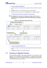
Page 617: ...ng and media A device located behind a NAT that initiates a signaling path has problems in receiving incoming signaling responses they are blocked by the NAT server Furthermore the initiating device must notify the receiving device where to send the media To resolve these issues the following mechanisms are available First Incoming Packet Mechanism see First Incoming Packet Mechanism on page 617 R...

Page 618: ...t frame including duplication of the sequence number Note Receipt of No Op packets is always supported 9 2 Robust Receipt of Media Streams This mechanism filters out unwanted media i e RTP RTCP and T 38 streams that are sent to the same port number on the device These multiple media streams can result from traces of previous calls call control errors and deliberate attacks When more than one media...

Page 619: ... devices to that network and intercommunicate using a dynamic routing protocol the routers can determine the shortest path to a certain destination and signal the remote host the existence of the better route Using multiple router support the device can utilize these router messages to change its next hop and establish the best path Note Multiple Routers support is an integral feature that doesn t...

Page 620: ...r causing the clock to update quicker and catch up to the correct time The advantage of this method is that it does not introduce any disparity in the system time that is noticeable to an end user or that could corrupt call timeouts and timestamps 9 5 Network Configuration The device allows you to configure up to 12 different IP addresses with associated VLANs for the VoIP network using the Multip...

Page 621: ...Control IPv4 10 32 174 50 16 0 0 0 0 5 ControlIF 2 Media IPv4 10 33 174 50 16 10 33 0 1 6 Media1IF 3 Media IPv4 10 34 174 50 16 0 0 0 0 7 Media2IF 4 Media IPv4 10 35 174 50 16 10 35 0 1 8 Media3IF 5 Media IPv4 10 36 174 50 16 0 0 0 0 9 Media4IF 6 Media IPv4 10 37 174 50 16 0 0 0 0 10 Media5IF 7 Media IPv4 10 38 174 50 16 0 0 0 0 11 Media6IF 8 Media IPv4 10 39 174 50 16 10 39 0 1 12 Media7IF 9 Medi...

Page 622: ... SSH SNMP CONTROL Call Control protocols i e SIP MEDIA RTP streams of voice Various combinations of the above mentioned types The following table shows the possible values of this column and their descriptions Table 9 2 Application Types Value Description 0 OAMP only OAMP applications are allowed on this interface 1 MEDIA only Media RTP are allowed on this interface 2 CONTROL only Call Control app...

Page 623: ...1100 Each interface must have its own address space Two interfaces may not share the same address space or even part of it The IP address should be configured as a dotted decimal notation For IPv4 interfaces the prefix length values range from 0 to 30 For IPv6 interfaces the prefix length must be set to 64 9 5 1 2 5 Gateway Column This column defines a default gateway for each interface A default ...

Page 624: ...alm table This column must have a unique value for each interface no two interfaces can have the same name and must not be left blank 9 5 1 3 Other Related Parameters The Multiple Interface table allows you to configure interfaces and their related parameters such as VLAN ID default gateway or interface name This section lists additional parameters complementing this table functionality 9 5 1 3 1 ...

Page 625: ...es i e indices 0 63 The valid range of the parameter DiffServ is 0 63 The valid range of the parameter VlanPriority is 0 7 To set a default VLAN Priority used for ARPs and automated ICMP packets as well as for IP Packets without DiffServ value set a VLAN Priority value for DiffServ 0 Layer 3 Class Of Service Parameters TOS DiffServ PremiumServiceClassMediaDiffServ Defines the DiffServ value for Pr...

Page 626: ...ze NTP Varies according to NTP settings EnableNTPasOAM OAMP Control Depends on traffic type Control Premium control Management Bronze 9 5 1 3 3 Applications with Assignable Application Type Some applications can be associated with different application types in different setups These application types are configurable The applications listed below can be configured to one of two application types ...

Page 627: ...faces with Application Types MEDIA with VLANs One IPv4 interface with Application Types OAMP MEDIA one other or more IPv4 interfaces with Application Types MEDIA CONTROL Other configurations are also possible while keeping to the above mentioned rule Each network interface may be defined with a default gateway This default gateway address must be in the same subnet as the associated interface Addi...

Page 628: ...pplication Types of OAMP Only one interface defined but the Application Types column is not set to OAM Media Control numeric value 6 An IPv4 interface was defined with Interface Type different than IPv4 Manual 10 Two interfaces have the exact VLAN ID value Two interfaces have the same name Two interfaces share the same address space or subnet Apart from these validation errors connectivity problem...

Page 629: ...CIDR style representation of a dotted decimal subnet notation The CIDR style representation uses a suffix indicating the number of bits that are set in the dotted decimal format For example 16 is synonymous with subnet 255 255 0 0 9 5 2 2 3 Gateway Column The Gateway column defines the IP address of the next hop used for traffic destined to the subnet host as defined in the destination mask column...

Page 630: ...tive 9 5 2 3 Routing Table Configuration Summary and Guidelines The Routing table configurations must adhere to the following rules Up to 30 different static routing rules may be defined The Prefix Length replaces the dotted decimal subnet mask presentation This column must have a value of 0 31 for IPv4 interfaces and a value of 64 for IPv6 interfaces The Gateway IP Address must be on the same sub...

Page 631: ...ly the route is not added and the device is not accessible remotely To restore connectivity the device must be accessed locally from the OAMP subnet and the required routes be configured 9 5 3 Setting Up VoIP Networking 9 5 3 1 Using the Web Interface The Web interface is a convenient user interface for configuring the device s network configuration 9 5 3 2 Using the ini File When configuring the ...

Page 632: ...A Multiple Interface table with a an interface for OAMP applications 192 168 0 2 16 an interface for Media Control applications 10 32 174 50 24 an interface for Media applications 10 33 174 50 24 and an interface for Control applications 10 34 174 50 24 Each interface is defined with its own VLAN ID Default Gateway and name A Routing table is configured with three static routing rules Directing al...

Page 633: ...ex Allowed Applications Interface Mode IP Address Prefix Length Default Gateway VLAN ID Interface Name 0 OAMP Media Control IPv4 192 168 0 2 16 192 168 0 1 1 myInterface Additional static routing rules Table 9 10 Routing Table Example 1 Destination Prefix Length Gateway Interface Metric 201 201 0 0 16 192 168 11 10 0 1 202 202 0 0 16 192 168 11 1 0 1 The DNS NTP applications remain with their defa...

Page 634: ...ng Table Example2 Destination Prefix Length Gateway Interface Metric 176 85 49 0 24 192 168 11 1 0 1 All other parameters are set to their respective default values The DNS NTP applications are left with their default application types The corresponding ini file configuration is shown below Interface Table Configuration InterfaceTable FORMAT InterfaceTable_Index InterfaceTable_ApplicationTypes Int...

Page 635: ...0 0 1 All other parameters are set to their respective default values The DNS NTP applications are left with their default application types The corresponding ini file configuration is shown below Interface Table Configuration InterfaceTable FORMAT InterfaceTable_Index InterfaceTable_ApplicationTypes InterfaceTable_InterfaceMode InterfaceTable_IPAddress InterfaceTable_PrefixLength InterfaceTable_G...

Page 636: ...SIP User s Manual 636 Document LTRT 12804 Mediant 800 MSBG Reader s Notes ...

Page 637: ...ng clock from the PSTN line Trunk interface For a full description of the clock parameters see PSTN Parameters on page 783 TDMBusClockSource 4 Network recovers clock from line interface ClockMaster configures the PSTN trunk to recover derive clock from the device or transmit the clock to the remote side of the PSTN trunk i e clock slave or clock master ClockMaster_x 0 1 where x depicts the trunk n...

Page 638: ...e Cause Use the parameter DefaultCauseMapISDN2IP described in ISDN and CAS Interworking Parameters on page 799 to define a default ISDN Cause that is always used except when the following Release Causes are received Normal Call Clearing 16 User Busy 17 No User Responding 18 or No Answer from User 19 This mechanism is only available for Tel to IP calls 10 2 1 Reason Header The device supports the R...

Page 639: ...ged w o diagnostic 410 Gone 26 Non selected user clearing 404 Not found 27 Destination out of order 502 Bad gateway 28 Address incomplete 484 Address incomplete 29 Facility rejected 501 Not implemented 30 Response to status enquiry 501 Not implemented 31 Normal unspecified 480 Temporarily unavailable 34 No circuit available 503 Service unavailable 38 Network out of order 503 Service unavailable 41...

Page 640: ...d call identity has been cleared 408 Request timeout 87 User not member of CUG 503 Service unavailable 88 Incompatible destination 503 Service unavailable 91 Invalid transit network selection 502 Bad gateway 95 Invalid message 503 Service unavailable 96 Mandatory information element is missing 409 Conflict 97 Message type non existent or not implemented 480 Temporarily not available 98 Message not...

Page 641: ...imer expiry 409 Conflict 41 Temporary failure 410 Gone 22 Number changed w o diagnostic 411 Length required 127 Interworking 413 Request entity too long 127 Interworking 414 Request URI too long 127 Interworking 415 Unsupported media type 79 Service option not implemented 420 Bad extension 127 Interworking 480 Temporarily unavailable 18 No user responding 481 Call leg transaction doesn t exist 127...

Page 642: ...out configured by the TimeBetweenDigits parameter expires The maximum allowed number of digits configured by the MaxDigits parameter is reached A match is found with the defined digit map configured by the DigitMapping parameter The device can also mute in band DTMF detection until the device receives the full destination number from the ISDN This is configured using the MuteDTMFInOverlap paramete...

Page 643: ...nt T1 trunks Each T1 trunk is called an NFAS member The T1 trunk whose D channel is used for signaling is called the Primary NFAS Trunk The T1 trunk whose D channel is used for backup signaling is called the Backup NFAS Trunk The primary and backup trunks each carry 23 B channels while all other NFAS trunks each carry 24 B channels The NFAS group is identified by an NFAS GroupID number possible va...

Page 644: ...1 trunks that doesn t contain the D channel Calls initiated on B channels of the Primary T1 trunk by default don t contain the Interface Identifier Setting the parameter ISDNIBehavior_x to 2048 forces the inclusion of the Channel Identifier parameter also for the Primary trunk The parameter ISDNNFASInterfaceID_x ID can define the Interface ID for any Primary T1 trunk even if the T1 trunk is not a ...

Page 645: ... procedures for creating and deleting an NFAS group must be performed in the correct order as described below To create an NFAS Group 1 If there s a backup secondary trunk for this group it must be configured first 2 Configure the primary trunk before configuring any NFAS slave trunk 3 Configure NFAS slave trunks To stop delete an NFAS Group 1 Stop or delete by setting ProtocolType to 0 i e None a...

Page 646: ...nsates for near far gain differences AGC estimates the energy of the incoming signal from the IP or PSTN determined by the parameter AGCRedirection calculates the essential gain and then performs amplification Feedback ensures that the output signal is not clipped You can define the required Gain Slope in decibels per second using the parameter AGCGainSlop and the required signal energy threshold ...

Page 647: ...Routing Table is used to define the destination IP address of the terminating device The terminating device automatically answers these calls if its E1 T1 protocol type is set to Transparent ProtocolType 5 or Raw CAS ProtocolType 3 for T1 and 9 for E1 and the parameter ChannelSelectMode is set to 0 By Phone Number Note It s possible to configure both devices to also operate in symmetric mode To do...

Page 648: ...leTDMOverIP 1 E1_TRANSPARENT_31 ProtocolType_0 5 ProtocolType_1 5 ProtocolType_2 5 ProtocolType_3 5 PREFIX FORMAT PREFIX_Index PREFIX_DestinationPrefix PREFIX_DestAddress PREFIX_SourcePrefix PREFIX_ProfileId PREFIX_MeteringCode PREFIX_DestPort Prefix 1 10 8 24 12 PREFIX IP address of the device in the opposite location Channel selection by Phone number ChannelSelectMode 0 Profiles can be used do d...

Page 649: ...Channel TrunkGroup_LastBChannel TrunkGroup_FirstPhoneNumber TrunkGroup_ProfileId TrunkGroup_Module TrunkGroup 0 0 0 0 1 31 1000 1 TrunkGroup 0 0 1 1 1 31 2000 1 TrunkGroup 0 0 2 2 1 31 3000 1 TrunkGroup 0 0 3 1 31 4000 1 TrunkGroup 0 0 0 0 16 16 7000 2 TrunkGroup 0 0 1 1 16 16 7001 2 TrunkGroup 0 0 2 2 16 16 7002 2 TrunkGroup 0 0 3 3 16 16 7003 2 TrunkGroup CodersGroup0 FORMAT CodersGroup0_Index C...

Page 650: ...Tel The term tunneling means that messages are transferred as is to the remote side without being converted QSIGÆSIPÆQSIG The advantage of tunneling over QSIG to SIP interworking is that by using interworking QSIG functionality can only be partially achieved When tunneling is used all QSIG capabilities are supported whereas the tunneling medium the SIP network does not need to process these messag...

Page 651: ...rameter to 128 duplicate all messages Set the ISDNInCallsBehavior parameter to 4096 Set the ISDNRxOverlap parameter 0 for tunneling of QSIG overlap dialed digits see below for description For a detailed description of these parameters see ISDN and CAS Interworking Parameters on page 799 The configuration of the ISDNInCallsBehavior and ISDNRxOverlap parameters as mentioned above allows tunneling of...

Page 652: ...SIP User s Manual 652 Document LTRT 12804 Mediant 800 MSBG Reader s Notes ...

Page 653: ...ble parameter configures the Multiple Interface table for configuring the IP addresses of the voice and or data functionalities and logical IP addresses The format of this parameter is as follows InterfaceTable FORMAT InterfaceTable_Index InterfaceTable_ApplicationTypes InterfaceTable_InterfaceMode InterfaceTable_IPAddress InterfaceTable_PrefixLength InterfaceTable_Gateway InterfaceTable_VlanID In...

Page 654: ...ype for DNS services 1 OAMP default 0 Control Note For this parameter to take effect a device reset is required EnableNTPasOAM Determines the application type for NTP services 1 OAMP default 0 Control Note For this parameter to take effect a device reset is required 12 1 2 VoIP Static Routing Parameters The static routing parameters are described in the table below Table 12 2 Static Routing Parame...

Page 655: ...ed for RTP Media traffic Premium Control Service class used for Call Control traffic Gold Service class used for streaming applications Bronze Service class used for OAMP applications The Layer 3 QoS parameters enables setting the values of the DiffServ field in the IP Header of the frames related to a specific service class The Layer 2 QoS parameters enable setting the values for the 3 priority b...

Page 656: ...by the following according to priority 9 IPDiffServ value in the selected IP Profile IPProfile parameter 9 PremiumServiceClassMediaDiffServ Web Control Premium QoS EMS Premium Service Class Control Diff Serv PremiumServiceClassControlDiffServ Defines the DiffServ value for Premium Control CoS content Call Control applications The valid range is 0 to 63 The default value is 40 Notes For this parame...

Page 657: ...nable 1 Disable default Web NAT IP Address EMS Static NAT IP Address StaticNatIP Global public IP address of the device to enable static NAT between the device and the Internet Note For this parameter to take effect a device reset is required Web EMS Inbound Media Latch Mode InboundMediaLatchMode Enables or disables the receipt of media streams whose IP address port are not configured for the chan...

Page 658: ...ed by the NFS file server that needs to be accessed by the device The format of this ini file table parameter is as follows NFSServers FORMAT NFSServers_Index NFSServers_HostOrIP NFSServers_RootPath NFSServers_NfsVersion NFSServers_AuthType NFSServers_UID NFSServers_GID NFSServers_VlanType NFSServers For example NFSServers 1 101 1 13 audio1 3 1 0 1 1 Notes You can configure up to 16 NFS file syste...

Page 659: ...different IP addresses in dotted decimal notation can be assigned to a host name The format of this parameter is as follows Dns2Ip FORMAT Dns2Ip_Index Dns2Ip_DomainName Dns2Ip_FirstIpAddress Dns2Ip_SecondIpAddress Dns2Ip_ThirdIpAddress Dns2Ip_FourthIpAddress Dns2Ip For example Dns2Ip 0 DnsName 1 1 1 1 2 2 2 2 3 3 3 3 4 4 4 4 Notes This parameter can include up to 20 indices If the internal DNS tab...

Page 660: ... ini File Table Parameters on page 368 12 1 7 DHCP Parameters The Dynamic Host Control Protocol DHCP parameters are described in the table below Table 12 7 DHCP Parameters Parameter Description Web Enable DHCP EMS DHCP Enable DHCPEnable Determines whether Dynamic Host Control Protocol DHCP is enabled 0 Disable Disable DHCP support on the device default 1 Enable Enable DHCP support on the device No...

Page 661: ...Note For detailed information on Network Time Protocol NTP see Simple Network Time Protocol Support on page 619 Web NTP Server IP Address EMS Server IP Address NTPServerIP The IP address in dotted decimal notation of the NTP server The default IP address is 0 0 0 0 i e internal NTP client is disabled Web NTP UTC Offset EMS UTC Offset NTPServerUTCOffset Defines the Universal Time Coordinate UTC off...

Page 662: ...efault value is 0 0 0 0 i e the device can be accessed from any IP address For example WebAccessList_0 10 13 2 66 WebAccessList_1 10 13 77 7 For defining the Web and Telnet Access list using the Web interface see Configuring Web and Telnet Access List on page 77 Web Use RADIUS for Web Telnet Login EMS Web Use Radius Login WebRADIUSLogin Uses RADIUS queries for Web and Telnet interface authenticati...

Page 663: ...de 0 Enables modifications of parameters default 1 Web interface in read only mode When in read only mode parameters can t be modified In addition the following pages can t be accessed Web User Accounts Certificates Regional Settings Maintenance Actions and all file loading pages Load Auxiliary Files Software Upgrade Wizard and Configuration File Note For this parameter to take effect a device res...

Page 664: ...he LAN interface Table 12 11 Telnet Parameters Parameter Description Web Embedded Telnet Server EMS Server Enable TelnetServerEnable Enables or disables the device s embedded Telnet server Telnet is disabled by default for security 0 Disable default 1 Enable Unsecured 2 Enable Secured SSL Note Only the primary Web User Account which has Security Administration access level can access the device us...

Page 665: ...eLanWatchDog Determines whether the LAN Watch Dog feature is enabled 0 Disable Disable LAN Watch Dog default 1 Enable Enable LAN Watch Dog When LAN Watch Dog is enabled the device s overall communication integrity is checked periodically If no communication is detected for about three minutes the device performs a self test If the self test succeeds the problem is a logical link down i e Ethernet ...

Page 666: ...default value is 7 seconds Note This feature helps overcome connection problems caused by some LAN routers or IP configuration parameters modifications by a DHCP server 12 3 2 Syslog CDR and Debug Parameters The Syslog CDR and debug parameters are described in the table below Table 12 13 Syslog CDR and Debug Parameters Parameter Description Web Enable Syslog EMS Syslog enable EnableSyslog Sends th...

Page 667: ... logs are sent The default value is a null string which causes CDR messages to be sent with all Syslog messages to the Syslog server Notes The CDR messages are sent to UDP port 514 default Syslog port This mechanism is active only when Syslog is enabled i e the parameter EnableSyslog is set to 1 Web EMS CDR Report Level CDRReportLevel Determines whether Call Detail Records CDR are sent to the Sysl...

Page 668: ...is is useful for example if you collect the device s and other equipments Syslog messages at one single server The device s Syslog messages can easily be identified and distinguished from other Syslog messages by its Facility level Therefore in addition to filtering Syslog messages according to IP address the messages can be filtered according to Facility level 16 local use 0 local0 default 17 loc...

Page 669: ...e default 1 Enable Note For this feature to be functional the GWDebugLevel parameter must be enabled i e set to at least level 1 12 3 3 Remote Alarm Indication Parameters The Remote Alarm Indication RAI parameters are described in the table below Table 12 14 RAI Parameters Parameter Description EnableRAI Enables RAI alarm generation if the device s busy endpoints exceed a user defined threshold 0 ...

Page 670: ...rial port is disabled default The RS 232 serial port can be used to change the networking parameters and view error notification messages For information on establishing a serial communications link with the device refer to the Installation Manual Note For this parameter to take effect a device reset is required EMS Baud Rate SerialBaudRate Determines the value of the RS 232 baud rate The valid va...

Page 671: ...t rules further down the table are ignored If the end of the table is reached without a match the packet is accepted The format of this parameter is as follows AccessList FORMAT AccessList_Index AccessList_Source_IP AccessList_PrefixLen AccessList_Start_Port AccessList_End_Port AccessList_Protocol AccessList_Use_Specific_Interface AccessList_Interface_ID AccessList_Packet_Size AccessList_Byte_Rate...

Page 672: ...or ARIA encryption for TLS The only ciphers available are RC4 and DES and the cipher bit strength is limited to 56 bits Notes If the Strong Encryption Software Upgrade Key is enabled the default of the HTTPSCipherString parameter is changed to RC4 EXP enabling RC 128bit encryption The value ALL can be configured only if the Strong Encryption Software Upgrade Key is enabled Web HTTP Authentication ...

Page 673: ...ished Incoming calls that don t include encryption information are accepted default 1 Mandatory The device initiates encrypted calls but if negotiation of the cipher suite fails the call is terminated Incoming calls that don t include encryption information are rejected 2 Disable The profile does not support encrypted calls i e SRTP 3 Preferable Single Media The device sends SDP with a single medi...

Page 674: ...12 4 4 TLS Parameters The Transport Layer Security TLS parameters are described in the table below Table 12 19 TLS Parameters Parameter Description Web EMS TLS Version TLSVersion Defines the supported versions of SSL TLS Secure Socket Layer Transport Layer Security 0 SSL 2 0 3 0 and TLS 1 0 SSL 2 0 SSL 3 0 and TLS 1 0 are supported default 1 TLS 1 0 Only only TLS 1 0 is used When set to 0 SSL TLS ...

Page 675: ...o use wildcards to replace parts of the domain name If the SubjectAltName is not marked as critical and there is no match the CN value of the SubjectName field is compared with the parameter TLSRemoteSubjectName If a match is found the connection is established Otherwise the connection is terminated Web TLS Client Verify Server Certificate EMS Verify Server Certificate VerifyServerCertificate Dete...

Page 676: ... to the Product Reference Manual SSHMaxLoginAttempts Defines the maximum SSH login attempts allowed for entering an incorrect password by an administrator before the SSH session is rejected The valid range is 1 to 3 the default is 3 SSHEnableLastLoginMessage Enables or disables the message display in SSH sessions of the time and date of the last SSH login The SSH login message displays the number ...

Page 677: ...ultResponse Determines the default OCSP behavior when the server cannot be contacted 0 Rejects peer certificate default 1 Allows peer certificate 12 5 RADIUS Parameters The RADIUS parameters are described in the table below For detailed information on the supported RADIUS attributes see Supported RADIUS Attributes on page 609 Table 12 22 RADIUS Parameters Parameter Description Web Enable RADIUS Ac...

Page 678: ...ort RADIUSAuthPort RADIUS Authentication Server Port Note For this parameter to take effect a device reset is required Web RADIUS Shared Secret SharedSecret Secret used to authenticate the device to the RADIUS server This should be a cryptically strong password Web Default Access Level DefaultAccessLevel Defines the default access level for the device when the RADIUS authentication response doesn ...

Page 679: ... default port is 161 Note For this parameter to take effect a device reset is required SNMPTrustedMGR_x Defines up to five IP addresses of remote trusted SNMP managers from which the SNMP agent accepts and processes SNMP Get and Set requests Notes By default the SNMP agent accepts SNMP Get and Set requests from any IP address as long as the correct community string is used in the request Security ...

Page 680: ... is required acUserInputAlarmDescription Defines the description of the input alarm acUserInputAlarmSeverity Defines the severity of the input alarm AlarmHistoryTableMaxSize Determines the maximum number of rows in the Alarm History table This parameter can be controlled by the Config Global Entry Limit MIB located in the Notification Log MIB The valid range is 50 to 1000 The default value is 500 ...

Page 681: ...P Manager 0 Disable Sending is disabled 1 Enable Sending is enabled default SNMPManagerTrapUser_x This parameter can be set to the name of any configured SNMPV3 user to associate with this trap destination This determines the trap format authentication level and encryption level By default the trap is associated with the SNMP trap community string Web Trap Manager Host Name SNMPTrapManagerHostName...

Page 682: ...page 81 For an explanation on using ini file table parameters see Configuring ini File Table Parameters on page 368 12 7 SIP Media Realm Parameters The SIP Media Realm parameters are described in the table below Table 12 24 SIP Media Realm Parameters Parameter Description Web Default CP Media Realm Name EMS Default Realm Name cpDefaultMediaRealmName For a description of this parameter see Configur...

Page 683: ... precedence For a detailed description of all the parameters included in this ini file table parameter and for configuring Media Realms using the Web interface see Configuring Media Realms on page 109 For a description on configuring ini file table parameters see Configuring ini File Table Parameters on page 368 12 8 Control Network Parameters 12 8 1 IP Group Proxy Registration and Authentication ...

Page 684: ...er name and password for authenticating each device port The format of this parameter is as follows Authentication FORMAT Authentication_Index Authentication_UserId Authentication_UserPassword Authentication_Module Authentication_Port Authentication Where UserId User name UserPassword Password Module Module number where 1 depicts the module in Slot 1 Port Port number where 1 depicts the Port 1 of ...

Page 685: ...plicationType Account For example Account 1 1 1 1 user 1234 acl 1 ITSP1 0 Notes This table can include up to 32 indices where 1 is the first index You can define multiple table indices with the same ServedTrunkGroup but different ServingIPGroups username password HostName and ContactUser This provides the capability for registering the same Hunt Group or IP Group to several ITSP s i e Serving IP G...

Page 686: ...lbackUsed Determines whether the device falls back to the Outbound IP Routing Table for call routing when Proxy servers are unavailable 0 Disable Fallback is not used default 1 Enable The Outbound IP Routing Table is used when Proxy servers are unavailable When the device falls back to the Outbound IP Routing Table it continues scanning for a Proxy When the device locates an active Proxy it switch...

Page 687: ...direct calls This parameter is disregarded if the parameter AlwaysSendToProxy is set to 1 Web EMS DNS Query Type DNSQueryType Enables the use of DNS Naming Authority Pointer NAPTR and Service Record SRV queries to resolve Proxy and Registrar servers and to resolve all domain names that appear in the SIP Contact and Record Route headers 0 A Record default 1 SRV 2 NAPTR If set to A Record 0 no NAPTR...

Page 688: ... type If the Proxy IP address parameter contains a domain name with port definition e g ProxyIP domain com 5080 the device performs a regular DNS A record query If a specific Transport Type is defined a NAPTR query is not performed Note When enabled NAPTR SRV queries are used to discover Proxy servers even if the parameter DNSQueryType is disabled Web EMS Graceful Busy Out Timeout sec GracefulBusy...

Page 689: ...The value is free format i e Cnonce 0a4f113b The default is Default_Cnonce Web EMS Mutual Authentication Mode MutualAuthenticationMode Determines the device s mode of operation when Authentication and Key Agreement AKA Digest Authentication is used 0 Optional Incoming requests that don t include AKA authentication information are accepted default 1 Mandatory Incoming requests that don t include AK...

Page 690: ...t ID table using the Web interface and for a detailed description of the parameters of this ini file table see Configuring Proxy Sets Table on page 126 For an explanation on using ini file table parameters see Configuring ini File Table Parameters on page 368 Web Proxy Set Table EMS Proxy Set ProxySet This ini file table parameter configures the Proxy Set ID table It is used in conjunction with th...

Page 691: ...EMS Registrar Name RegistrarName Registrar domain name If specified the name is used as the Request URI in REGISTER messages If it isn t specified default the Registrar IP address or Proxy name or IP address is used instead The valid range is up to 49 characters Web Registrar IP Address EMS Registrar IP RegistrarIP The IP address or FQDN and port number optional of the Registrar server The IP addr...

Page 692: ...ote This parameter may be overridden if the parameter RegistrationTimeThreshold is greater than 0 Web EMS Registration Retry Time RegistrationRetryTime Defines the time interval in seconds after which a registration request is re sent if registration fails with a 4xx response or if there is no response from the Proxy Registrar server The default is 30 seconds The range is 10 to 3600 Web Registrati...

Page 693: ...SIP re registration upon TCP TLS connection failure 0 Disable default 1 Enable Web Gateway Registration Name EMS Name GWRegistrationName Defines the user name that is used in the From and To headers in SIP REGISTER messages If no value is specified default for this parameter the UserName parameter is used instead Note This parameter is applicable only for single registration per device i e Authent...

Page 694: ...n bindings When enabled the device removes SIP User Agent UA registration bindings in a Registrar according to RFC 3261 Registrations are soft state and expire unless refreshed but they can also be explicitly removed A client can attempt to influence the expiration interval selected by the Registrar A UA requests the immediate removal of a binding by specifying an expiration interval of 0 for that...

Page 695: ...ypes such as TCP 0 Disable default 1 Enable The SIP user agent client i e device uses a simple periodic message as a keep alive mechanism to keep their flow to the proxy or registrar alive used for example to keep NAT bindings open For connection oriented transports such as TCP TLS this is based on CRLF This mechanism uses a client to server ping keep alive and a corresponding server to client pon...

Page 696: ...f this parameter is as follows SRD FORMAT SRD_Index SRD_Name SRD_MediaRealm SRD_IntraSRDMediaAnchoring SRD_BlockUnRegUsers SRD_MaxNumOfRegUsers SRD_EnableUnAuthenticatedRegistrations SRD For example SRD 1 LAN1_SRD Mrealm1 0 1 15 1 SRD 2 LAN2_SRD Mrealm2 0 1 15 1 Notes This table can include up to 32 indices where 0 is the first index For a detailed description of the table s individual parameters ...

Page 697: ...nd topology hiding of internal IP addresses to the public network Each IP interface configured in the Multiple Interface table InterfaceTable parameter can be associated with a NAT rule in this table translating the source IP address and port of the outgoing packet into the NAT address IP address and port range The format of this parameter is as follows NATTranslation FORMAT NATTranslation_Index N...

Page 698: ...SIP requests are received even if the rport parameter is not present in the Via header Web Max Number of Active Calls EMS Maximum Concurrent Calls MaxActiveCalls Defines the maximum number of simultaneous active calls supported by the device If the maximum number of calls is reached new calls are not established The valid range is 1 to the maximum number of supported channels The default value is ...

Page 699: ...P Stat PS 207 OS 49680 PR 314 OR 50240 PL 0 JI 600 LA 40 Supported em timer replaces path resource priority Allow REGISTER OPTIONS INVITE ACK CANCEL BYE NOTIFY PRACK REFER INFO SUBSCRIBE UPDATE User Agent Sip Gateway v 6 2A 008 006 Reason Q 850 cause 16 text local Content Length 0 Web EMS PRACK Mode PrackMode PRACK Provisional Acknowledgment mechanism mode for SIP 1xx reliable responses 0 Disable ...

Page 700: ...gain Therefore this feature reduces clipping of early media Notes To enable this feature configure the EnableEarlyMedia parameter to 1 This feature is applicable only to ISDN interfaces Web 183 Message Behavior EMS SIP 183 Behaviour SIP183Behaviour Digital interfaces Defines the ISDN message that is sent when the 183 Session Progress message is received for IP to Tel calls Analog interfaces Define...

Page 701: ...that no user part in the Request URI host part only is used The valid range is a 30 character string The default value is an empty string Web Fax Signaling Method EMS Fax Used IsFaxUsed Determines the SIP signaling method for establishing and transmitting a fax session after a fax is detected 0 No Fax No fax negotiation using SIP signaling Fax transport method is according to the parameter FaxTran...

Page 702: ...S TCP Local SIP Port TCPLocalSIPPort Local TCP port for SIP messages The valid range is 1 to 65535 The default value is 5060 Web SIP TLS Local Port EMS TLS Local SIP Port TLSLocalSIPPort Local TLS port for SIP messages The valid range is 1 to 65535 The default value is 5061 Note The value of this parameter must be different from the value of the parameter TCPLocalSIPPort Web EMS Enable SIPS Enable...

Page 703: ...n Port EMS Destination Port SIPDestinationPort SIP destination port for sending initial SIP requests The valid range is 1 to 65534 The default port is 5060 Note SIP responses are sent to the port specified in the Via header Web Use user phone in SIP URL EMS Is User Phone IsUserPhone Determines whether the user phone string is added to the SIP URI and SIP To header 0 No user phone string is not add...

Page 704: ...able 487 Request Terminated 486 Busy Here Call Forward Busy CFB 600 Busy Everywhere If history reason is a Q 850 reason it is translated to the SIP reason according to the SIP ISDN tables and then to ISDN Redirect reason according to the table above User Agent Server UAS Behavior The History Info header is sent only in the final response Upon receiving a request with History Info the UAS checks th...

Page 705: ...P address The source trunk group ID is the Hunt Group ID where incoming calls from Tel is received For IP Tel calls the SIP 200 OK device s response contains tgrp destination trunk group ID trunk context gateway IP address The destination trunk group ID is the Hunt Group ID used for outgoing Tel calls The gateway IP address in trunk context can be configured using the parameter SIPGatewayName 3 Ho...

Page 706: ...el calls according to the Inbound IP Routing Table or according to the SIP tgrp parameter 0 default IP to Tel routing is determined by the Inbound IP Routing Table PSTNPrefix parameter If a matching rule is not found in this table the device uses the Hunt Group parameters for routing the call 1 The device first places precedence on the tgrp parameter for IP to Tel routing If the received INVITE Re...

Page 707: ...sable by anyone It needs to be a GRUU Obtaining a GRUU The mechanism for obtaining a GRUU is through registrations A UA can obtain a GRUU by generating a REGISTER request containing a Supported header field with the value gruu The UA includes a sip instance Contact header parameter of each contact for which the GRUU is desired This Contact parameter contains a globally unique ID that identifies th...

Page 708: ... modified Therefore it is recommended not to include a forward slash in the parameter s value to avoid two forward slashes in the SIP header which may cause problems Web EMS SDP Session Owner SIPSDPSessionOwner Determines the value of the Owner line o field in outgoing SDP messages The valid range is a string of up to 39 characters The default value is AudiocodesGW For example o AudiocodesGW 11450...

Page 709: ...rected INVITE message default 1 Redirect Use the same call identifiers Web EMS Enable P Charging Vector EnablePChargingVector Enables the inclusion of the P Charging Vector header to all outgoing INVITE messages 0 Disable default 1 Enable Web EMS Retry After Time RetryAfterTime Determines the time in seconds used in the Retry After header when a 503 Service Unavailable response is generated by the...

Page 710: ...equest URI header default Obtains the destination number from the user part of the Request URI 1 To header Obtains the destination number from the user part of the To header 2 P Called Party ID header Obtains the destination number from the P Called Party ID header Web EMS Forking Handling Mode ForkingHandlingMode Determines how the device handles the receipt of multiple SIP 18x forking responses ...

Page 711: ...s response to an incoming SDP that includes an IP address of 0 0 0 0 in the SDP s Connection Information field i e c IN IP4 0 0 0 0 0 Sets the IP address of the outgoing SDP s c field to 0 0 0 0 default 1 Sets the IP address of the outgoing SDP c field to the IP address of the device If the incoming SDP doesn t contain the a inactive line the returned SDP contains the a recvonly line Web EMS Enabl...

Page 712: ...age EnableUserInfoUsage Enables or disables the usage of the User Information which is loaded to the device in the User Information auxiliary file For a description on User Information see Loading Auxiliary Files on page 337 0 Disable default 1 Enable HandleReasonHeader Determines whether the device uses the value of the incoming SIP Reason header for Release Reason mapping 0 Disregard Reason head...

Page 713: ...ult for FXO interfaces is 1 The default for FXS interfaces is 0 0 No PI For IP to Tel calls the device sends a 180 Ringing response to IP after placing a call to a phone FXS or PBX FXO 1 PI 1 8 PI 8 For IP to Tel calls if the parameter EnableEarlyMedia is set to 1 the device sends a 183 Session Progress message with SDP immediately after a call is placed to a phone PBX This is used to cut through ...

Page 714: ... negotiated with the remote side i e the selected payload type is according to the remote side selection The receiving device must include the Transparent coder in its coder list Web Enable RFC 4117 Transcoding EnableRFC4117Transco ding Enables transcoding of calls according to RFC 4117 0 Disable default 1 Enable Notes For this parameter to take effect a device reset is required For a detailed des...

Page 715: ...E from Microsoft s application with the URI user part as INVITE sip 622125519100 ext 104 10 1 1 10 or INVITE tel 622125519100 ext 104 If the parameter EnableMicrosofExt is enabled the device modifies the called number by adding an e as the prefix removing the ext parameter and adding the extension number as the suffix e g e622125519100104 Once modified the device can then manipulate the number fur...

Page 716: ... using the CodersGroup parameter If the ComfortNoiseNegotiation parameter is enabled then the following occurs If the device is the initiator it sends a CN in the SDP only if the SCE of the codec is enabled If the remote UA responds with a CN in the SDP then CNG occurs otherwise CNG does not occur If the device is the receiver and the remote SIP UA does not send a CN in the SDP then no CNG occurs ...

Page 717: ...llect call the user disconnects the call by on hooking the phone The device notifies the softswitch or Application server of the unanswered collect call on hook by sending a SIP INFO message As a result the softswitch disconnects the call sends a BYE message to the device If the call is a regular incoming call and the FXS user on hooks the phone without intending to disconnect the call the softswi...

Page 718: ...eive Only receive RTP packets only Note The ID in the ini file parameter depicts the trunk number where 0 is the first trunk Web EMS Media IP Version Preference MediaIPVersionPreferen ce Determines the preferred RTP media IP addressing version for outgoing SIP calls This is indicated in the c field Connection Information of the SDP 0 Only IPv4 offer includes only IPv4 media IP addresses default 1 ...

Page 719: ...ot configured i e default the SITQ850Cause parameter is used Web EMS SIT Q850 Cause For RO SITQ850CauseForRO Determines the Q 850 cause value specified in the SIP Reason header that is included in a 4xx response when SIT RO Reorder System Busy Special Information Tone is detected from the PSTN for IP to Tel calls The valid range is 0 to 127 The default value is 1 not configured Note When not confi...

Page 720: ...s 0 None Normal operation No response is provided to undefined endpoints A dial tone is played to FXS endpoints when a Busy Out condition exists 1 Reorder Tone The device plays a reorder tone to the connected phone PBX default 2 Polarity Reversal The device reverses the polarity of the endpoint marking it unusable relevant for example for PBX DID lines This option can t be configured on the fly 3 ...

Page 721: ...esponse for HotSwapRtx retransmissions to the INVITE message that is sent to the first IP address the device immediately initiates a call to the second IP address 12 10 Coders and Profile Parameters The profile parameters are described in the table below Table 12 28 Profile Parameters Parameter Description Web Coders Table Coder Group Settings EMS Coders Group CodersGroup0 CodersGroup1 CodersGroup...

Page 722: ...he supported coders Coder Name Packetization Time msec Rate kbps Payload Type Silence Suppression G 711 A law g711Alaw64k 10 20 default 30 40 50 60 80 100 120 Always 64 Always 8 Disable 0 Enable 1 G 711 U law g711Ulaw64k 10 20 default 30 40 50 60 80 100 120 Always 64 Always 0 Disable 0 Enable 1 G 722 g722 20 default 40 60 80 100 120 64 default Always 9 N A G 723 1 g7231 30 default 60 90 120 5 3 0 ...

Page 723: ... PLC capabilities ensuring higher voice quality A Coder Group can be assigned to an IP Profile using the IPProfile parameter and or to a Tel Profile using the TelProfile parameter For an explanation on V 152 support and implementation of T 38 and VBD coders see V 152 Support on page 452 For a description of using ini file table parameters see Configuring ini File Table Parameters on page 368 Web I...

Page 724: ...e IPProfile 1 ITSP 1 0 0 10 10 46 40 0 0 0 0 2 0 0 0 0 1 1 0 0 1 1 4 1 1 1 0 0 1 0 0 1 0 0 0 0 1 0 8 300 400 1 1 Notes You can configure up to nine IP Profiles i e indices 1 through 9 To use the settings of the corresponding global parameter enter the value 1 or in the Web interface the option Not Configured For a detailed description of each parameter see its corresponding global parameter IPProf...

Page 725: ...2IP IpProfile_EnableE arlyMedia Enable Early Media EnableEarlyMedia IpProfile_Progress Indicator2IP Progress Indicator to IP ProgressIndicator2I P IpProfile_EnableE choCanceller Echo Canceler EnableEchoCancell er IpProfile_CopyDes t2RedirectNumber Copy Destination Number to Redirect Number CopyDest2Redirect Number IpProfile_MediaSe curityBehaviour Media Security Behavior MediaSecurityBeha viour Ip...

Page 726: ... p0 IpProfile_SBCMedi aSecurityBehaviou r SBCMediaSecurity Behaviour IpProfile_SBCRFC 2833Behavior IpProfile_SBCAlter nativeDTMFMetho d IpProfile_SBCAss ertIdentity SBCAssertIdentity IpProfile_AMDSen sitivityParameterS uit AMD Sensitivity Level AMDSensitivityLeve l IpProfile_AMDSen sitivityLevel AMD Sensitivity Level AMDSensitivityLeve l IpProfile_AMDMax GreetingTime AMD Max Greeting Time AMDMaxGr...

Page 727: ...ers V21ModemTransportType V22ModemTransportType V23ModemTransportType V32ModemTransportType and V34ModemTransportType IP Profiles can also be used when operating with a Proxy server set the parameter AlwaysUseRouteTable to 1 The following parameters are not applicable IsDTMFUsed deprecated For a description of using ini file table parameters see Configuring ini File Table Parameters on page 368 We...

Page 728: ... or in the Web interface the option Not Configured For a detailed description of each parameter see its corresponding global parameter TelProfile Field Web Name Global Parameter TelProfile_ProfileN ame Profile Name TelProfile_TelPrefe rence Profile Preference TelProfile_Coders GroupID Coder Group CodersGroup0 TelProfile_IsFaxUs ed Fax Signaling Method IsFaxUsed TelProfile_JitterBu fMinDelay Dynami...

Page 729: ...file_TimeFor ReorderTone Time For Reorder Tone TimeForReorderTon e TelProfile_EnableD IDWink Enable DID Wink EnableDIDWink TelProfile_IsTwoSt ageDial Dialing Mode IsTwoStageDial TelProfile_Disconn ectOnBusyTone Disconnect Call on Detection of Busy Tone DisconnectOnBusy Tone TelProfile_EnableV oiceMailDelay Enable Voice Mail Delay TelProfile_DialPlan Index Dial Plan Index DialPlanIndex TelProfile_E...

Page 730: ... the same call the coders and common parameters i e parameters configurable in both IP and Tel Profiles of the preferred profile are applied to that call If the Tel and IP Profiles are identical the Tel Profile parameters take precedence The parameter EnableVoiceMailDelay is applicable only if voice mail is enabled globally using the VoiceMailInterface parameter For a description of using ini file...

Page 731: ...s parameter can also be configured per IP Profile using the IPProfile parameter see Configuring IP Profiles on page 143 and per Tel Profile using the TelProfile parameter see Configuring Tel Profiles on page 141 EMS Payload Format VoicePayloadFormat Determines the bit ordering of the G 726 G 727 voice payload format 0 Little Endian default 1 Big Endian Note To ensure high voice quality when using ...

Page 732: ...n is 1 annexb yes If EnableSilenceCompression is 2 and IsCiscoSCEMode is 0 annexb yes If EnableSilenceCompression is 2 and IsCiscoSCEMode is 1 annexb no Note This parameter can also be configured per IP Profile using the IPProfile parameter see Configuring IP Profiles on page 143 Web Echo Canceler EMS Echo Canceller Enable EnableEchoCanceller Enables or disables echo cancellation i e echo from voi...

Page 733: ...ported for EVRC and EVRC B coders EMS VBR Coder DTX Min EVRCDTXMin Defines the minimum gap between two SID frames when using the EVRC voice activity detector Units are in EVRC frame size 20 msec The range is 0 to 20000 The default value is 12 Note Supported for EVRC and EVRC B coders EMS VBR Coder DTX Max EVRCDTXMax Defines the maximum gap between two SID frames when using the EVRC voice activity ...

Page 734: ... To configure V34FaxTransportType to 1 i e fax relay you also need to configure FaxTransportMode to 1 fax relay Web Fax Relay Enhanced Redundancy Depth EMS Enhanced Relay Redundancy Depth FaxRelayEnhancedRedundanc yDepth Number of times that control packets are retransmitted when using the T 38 standard The valid range is 0 to 4 The default value is 2 Web Fax Relay Redundancy Depth EMS Relay Redun...

Page 735: ... device detects the fax Calling tone CNG 0 Disable The originating device doesn t detect CNG the CNG signal passes transparently to the remote side default 1 Relay CNG is detected on the originating side CNG packets are sent to the remote side according to T 38 if IsFaxUsed 1 and the fax session is started A SIP Re INVITE message isn t sent and the fax session starts by the terminating device This...

Page 736: ...sponding to 18 dBm to 3 dBm in 1 dB steps The default is 6 dBm fax gain control Web EMS Fax Bypass Output Gain FaxBypassOutputGain Defines the fax bypass output gain control The range is 31 to 31 dB in 1 dB steps The default is 0 i e no gain Web EMS Modem Bypass Output Gain ModemBypassOutputGain Defines the modem bypass output gain control The range is 31 dB to 31 dB in 1 dB steps The default is 0...

Page 737: ... A Law and 0 for G 711 μ Law The parameters defining payload type for the old Bypass mode FaxBypassPayloadType and ModemBypassPayloadType are not used with NSE Bypass The bypass packet interval is selected according to the FaxModemBypassBasicRtpPacketInterval parameter Notes This feature can be used only if the VxxModemTransportType parameter is set to 2 Bypass If NSE mode is enabled the SDP conta...

Page 738: ...so be configured per IP Profile using the IPProfile parameter see Configuring IP Profiles on page 143 Web V 32 Modem Transport Type EMS V32 Transport V32ModemTransportType V 32 Modem Transport Type used by the device 0 Disable Disable Transparent 1 Enable Relay N A 2 Enable Bypass default 3 Events Only Transparent with Events Notes This parameter applies only to V 32 and V 32bis modems This parame...

Page 739: ...w frequency components in the DTMF signal Positive decibel values cause the higher frequency component to be stronger than the lower one Negative values cause the opposite effect For any parameter value both components change so that their average is constant The valid range is 10 to 10 dB The default value is 0 dB Note For this parameter to take effect a device reset is required EMS DTMF Inter In...

Page 740: ... respectively For more information on Jitter Buffer see Dynamic Jitter Buffer Operation on page 412 Web EMS Analog Signal Transport Type AnalogSignalTransportType Determines the analog signal transport type 0 Ignore Analog Signals Ignore default 1 RFC 2833 Analog Signal Relay Transfer hookflash using RFC 2833 Web RTP Redundancy Depth EMS Redundancy Depth RTPRedundancyDepth Determines whether the d...

Page 741: ...t to 1 Web Packing Factor EMS Packetization Factor RTPPackingFactor N A Controlled internally by the device according to the selected coder Web EMS Basic RTP Packet Interval BasicRTPPacketInterval N A Controlled internally by the device according to the selected coder Web RTP Directional Control RTPDirectionControl N A Controlled internally by the device according to the selected coder Web EMS RFC...

Page 742: ...ed randomly to channels You can define a UDP port range per Media Realm see Configuring Media Realms on page 109 If RTP Base UDP Port is not a factor of 10 the following message is generated invalid local RTP port For detailed information on the default RTP RTCP T 38 port allocation refer to the Product Reference Manual EMS No Op Enable NoOpEnable Enables or disables the transmission of RTP or T 3...

Page 743: ...ge is 120 to 600 The default value is 560 Web EMS T38 Fax Max Buffer T38FaxMaxBufferSize Defines the maximum size in bytes of the device s T 38 buffer This value is included in the outgoing SDP when T 38 is used for fax relay over IP The valid range is 500 to 3000 The default value is 3000 Web EMS Enable Fax Re Routing EnableFaxReRouting Enables or disables re routing of Tel to IP calls that are i...

Page 744: ...8 for fax relay Notes For this parameter to take effect a device reset is required This parameters is applicable only if the parameter IsFaxUsed is set to 1 T 38 Relay or 3 Fax Fallback T38FaxSessionImmediateStart Enables fax transmission of T 38 no signal packets to the terminating fax machine 0 Disable default 1 Enable This is used for transmission from fax machines connected to the device locat...

Page 745: ...ing Note This parameter can also be configured per Tel Profile using the TelProfile parameter Web EMS Hook Flash Option HookFlashOption Determines the hook flash transport type i e method by which hook flash is sent and received 0 Not Supported Hook Flash indication isn t sent default 1 INFO Sends proprietary INFO message with Hook Flash indication 4 RFC 2833 5 INFO Lucent Sends proprietary SIP IN...

Page 746: ...9 Hook flash generation period upon detection of a SIP INFO message containing a hook flash signal FXO interfaces Hook flash generation period The valid range is 25 to 3 000 The default value is 700 Notes For this parameter to take effect you need to reset the device For FXO interfaces a constant of 100 msec must be added to the required hook flash period For example to generate a 450 msec hook fl...

Page 747: ...eter DTMFTransportType is automatically set to 0 DTMF digits are erased from the RTP stream When RFC 2833 4 is selected the device a Negotiates RFC 2833 payload type using local and remote SDPs b Sends DTMF packets using RFC 2833 payload type according to the payload type in the received SDP c Expects to receive RFC 2833 packets with the same payload type as configured by the parameter RFC2833Payl...

Page 748: ...port type is set according to the parameter DTMFTransportType and the DTMF digits aren t muted if out of band DTMF mode is selected TxDTMFOption set to 1 2 or 3 This enables the sending of DTMF digits in band transparent of RFC 2833 in addition to out of band DTMF messages Note Usually this mode is not recommended Web EMS Enable Digit Delivery to IP EnableDigitDelivery2IP The Digit Delivery featur...

Page 749: ...eset is required For analog interfaces The called number can include characters p 1 5 seconds pause and d detection of dial tone If character d is used it must be the first digit in the called number The character p can be used several times For example for FXS FXO interfaces the called number can be as follows d1005 dpp699 p9p300 To add the d and p digits use the usual number manipulation rules F...

Page 750: ...tion and Dial Plan Parameters Parameter Description Web EMS Dial Plan Index DialPlanIndex Determines the Dial Plan index to use in the external Dial Plan file The Dial Plan file is loaded to the device as a dat file converted using the DConvert utility The Dial Plan index can be defined globally or per Tel Profile The valid value range is 0 to 7 where 0 denotes PLAN1 1 denotes PLAN2 and so on The ...

Page 751: ... dot Repeat digits until next notation e g T x Any single digit T Dial timeout configured by the TimeBetweenDigits parameter S Short timer configured by the TimeBetweenDigits parameter default is two seconds that can be used when a specific rule is defined after a more general rule For example if the digit map is 99 998 then the digit collection is terminated after the first two 9 digits are recei...

Page 752: ...ern is matched Web Inter Digit Timeout for Overlap Dialing sec EMS Interdigit Timeout Sec TimeBetweenDigits For analog interfaces Defines the time in seconds that the device waits between digits that are dialed by the user For ISDN overlap dialing Defines the time in seconds that the device waits between digits that are received from the PSTN or IP during overlap dialing When this inter digit time...

Page 753: ...messages received from the Voice Mail server to an IP Group configured using the parameter NotificationIPGroupID 8 ETSI Euro ISDN according to ETS 300 745 1 V1 2 4 section 9 5 1 1 Enables MWI interworking from IP to Tel typically used for BRI phones Note To enable voice mail per Hunt Group you can use a Tel Profile ID using the TelProfile parameter that is configured with voice mail interface enab...

Page 754: ...rvised PBX Supervised transfer After receiving a REFER message from the IP side the FXO sends a hook flash to the PBX and then dials the digits that are received in the Refer To header The FXO waits for connection of the transfer call and if speech is detected e g hello within approximately 2 seconds the device completes the call transfer by releasing the line otherwise the transfer is cancelled t...

Page 755: ...20 character string Web Forward on No Reason Digit Pattern Internal EMS Digit Pattern Forward No Reason DigitPatternForwardNoReason Determines the digit pattern used by the PBX to indicate call forward with no reason when the original call is received from an internal extension The valid range is a 120 character string Web Forward on Busy Digit Pattern External EMS VM Digit Pattern On Busy Externa...

Page 756: ...lCall Determines the digit pattern used by the PBX to indicate an external call The valid range is a 120 character string Web Disconnect Call Digit Pattern EMS Tel Disconnect Code TelDisconnectCode Determines a digit pattern that when received from the Tel side indicates the device to disconnect the call The valid range is a 25 character string Web Digit To Ignore Digit Pattern EMS Digit To Ignore...

Page 757: ...ult 9 1 Enable enables Caller ID generation FXS or detection FXO Module Module number where 1 depicts the module in Slot 1 Port Port number where 1 depicts Port 1 of a module For example EnableCallerID 0 1 3 1 caller ID enabled on Port 1 of Module 3 EnableCallerID 1 0 3 2 caller ID disabled on Port 2 of Module 3 Notes The indexing of this parameter starts at 0 If a port is not configured its Calle...

Page 758: ...Caller ID for Port 2 of Module 1 Notes The indexing of this ini file table parameter starts at 0 When FXS ports receive Private or Anonymous strings in the SIP From header the calling name or number is not sent to the Caller ID display If the Caller ID name is detected on an FXO line the parameter EnableCallerID is set to 1 it is used instead of the Caller ID name defined in this table parameter W...

Page 759: ...cified signals 0 Standard Bellcore Caller ID and MWI default 1 Standard ETSI Caller ID and MWI 2 Standard NTT 4 Standard BT Britain 16 Standard DTMF Based ETSI 17 Standard Denmark Caller ID and MWI 18 Standard India 19 Standard Brazil Notes Typically the Caller ID signals are generated detected between the first and second rings However sometimes the Caller ID is detected before the first ring sig...

Page 760: ...t is sent to the FXS port in this example is 71137077801 If the incoming INVITE message doesn t contain the cpc parameter nothing is added to the Caller ID number CPC Value in Received INVITE CPC Code Prefixed to Caller ID Sent to FXS Endpoint Description cpc unknown 1 Unknown user cpc subscribe 1 cpc ordinary 1 Ordinary user cpc priority 2 Pre paid user cpc test 3 Test user cpc operator 5 Operato...

Page 761: ...ote For this parameter to take effect a device reset is required Web Asserted Identity Mode EMS Asserted ID Mode AssertedIdMode Determines whether the SIP header P Asserted Identity or P Preferred Identity is used in the generated INVITE request for Caller ID or privacy 0 Disabled None default 1 Adding PAsserted Identity 2 Adding PPreferred Identity This parameter determines the header P Asserted ...

Page 762: ...ertedIDMode to 1 This parameter is applicable to ISDN CAS and or FXO interfaces Web Caller ID Transport Type EMS Transport Type CallerIDTransportType Determines the device s behavior for Caller ID detection 0 Disable The caller ID signal is not detected DTMF digits remain in the voice stream 1 Relay Currently not applicable 3 Mute The caller ID signal is detected from the Tel PSTN side and then er...

Page 763: ...Port This ini file table parameter configures call waiting per FXS port The format of this parameter is as follows CallWaitingPerPort FORMAT CallWaitingPerPort_Index CallWaitingPerPort_IsEnabled CallWaitingPerPort_Module CallWaitingPerPort_Port CallWaitingPerPort Where IsEnabled 9 0 Disable no call waiting for the specific port 9 1 Enable enables call waiting for the specific port When the FXS dev...

Page 764: ...l waiting indication is played to the port that is currently in a call The valid range is 0 to 100 The default time is 0 seconds Note This parameter is applicable only to FXS ports Web EMS Waiting Beep Duration WaitingBeepDuration Duration in msec of call waiting indications that are played to the port that is receiving the call The valid range is 100 to 65535 The default value is 300 Note This pa...

Page 765: ...ribed in the table below Table 12 40 Call Forwarding Parameters Parameter Description Web Enable Call Forward EnableForward Determines whether Call Forward is enabled 0 Disable Disable the Call Forward service 1 Enable Enable Call Forward service using REFER default For FXS interfaces the Call Forward table FwdInfo parameter must be defined to use the Call Forward service Note To use this service ...

Page 766: ...alls originally destined to Port 1 of Module 1 to 1001 upon On Busy FwdInfo 0 1 1001 30 1 1 Below configuration forwards calls originally destined to Port 2 of Module 1 to an IP address upon On Busy FwdInfo 1 1 2003 10 5 1 1 30 1 2 Notes The indexing of this parameter starts at 0 Ensure that the Call Forward feature is enabled default for the settings of this table parameter to take effect To enab...

Page 767: ... EnableMWI Enables Message Waiting Indication MWI 0 Disable Disabled default 1 Enable MWI service is enabled Notes This parameter is applicable only to FXS interfaces The device supports only the receipt of SIP MWI NOTIFY messages the device doesn t generate these messages For detailed information on MWI see Message Waiting Indication on page 461 Web EMS MWI Analog Lamp MWIAnalogLamp Enables the v...

Page 768: ...o Not Configured the value of the parameter SIPTransportType is used Web MWI Subscribe Expiration Time EMS MWI Expiration Time MWIExpirationTime The MWI subscription expiration time in seconds The default is 7200 seconds The range is 10 to 2 000 000 Web MWI Subscribe Retry Time EMS Subscribe Retry Time SubscribeRetryTime Subscription retry time in seconds after last subscription failure The defaul...

Page 769: ...SDN to 1 For analog interfaces To use this service the devices at both ends must support this option This parameter can also be configured per IP Profile using the IPProfile parameter see Configuring IP Profiles on page 143 Web EMS Hold Format HoldFormat Determines the format of the SDP in the Re INVITE hold request 0 0 0 0 0 The SDP c field contains the IP address 0 0 0 0 and the a inactive attri...

Page 770: ... hold or there is a call waiting and the phone is changed from offhook to onhook the call is released and the device sends a SIP BYE to the IP Note This parameter is applicable only to FXS interfaces PlayDTMFduringHold Enables playing DTMF signals to the Tel side when a call is on hold 0 Disable default if the call is in Hold inactive state the device does not play DTMF signals to the Tel if it re...

Page 771: ...nfigure the parameter XferPrefixIP2Tel to 8 and the parameter TrunkTransferMode to 5 Web EMS Enable Semi Attended Transfer EnableSemiAttendedTransfer Determines the device behavior when Transfer is initiated while in Alerting state 0 Disable Send REFER with the Replaces header default 1 Enable Send CANCEL and after a 487 response is received send REFER without the Replaces header KeyBlindTransfer ...

Page 772: ...s parameter to take effect a device reset is required Web 3 Way Conference Mode EMS 3 Way Mode 3WayConferenceMode Defines the mode of operation when the 3 Way Conference feature is used 0 AudioCodes Media Server The Conference initiating INVITE sent by the device uses the ConferenceID concatenated with a unique identifier as the Request URI This same Request URI is set as the Refer To header value...

Page 773: ...ectly to PSAP DID loop start lines 0 Disable default 1 Enable Notes This parameter is applicable only to FXO interfaces This parameter can also be configured per Tel Profile using the TelProfile parameter Web EMS Emergency Numbers EmergencyNumbers Defines a list of emergency numbers When one of these numbers is dialed the outgoing INVITE message includes the SIP Priority and Resource Priority head...

Page 774: ...arty the device plays a reorder tone for a user defined time configured by the CutThroughTimeForReorderTone parameter and is then ready to answer the next incoming call without on hooking the phone The waiting call is automatically answered by the device when the current call is terminated configured by setting the parameter EnableCallWaiting to 1 Note This feature is applicable only to FXS interf...

Page 775: ...ination TargetOfChannel_Type TargetOfChannel_Module TargetOfChannel_Port TargetOfChannel_HotLineToneDuration TargetOfChannel Where Destination Destination phone number that you want dialed Type 9 0 Disable automatic dialing is disabled 9 1 Enable Destination phone number is automatically dialed if phone is off hooked for FXS interface or ring signal is applied to port FXO interface 9 2 Hotline ena...

Page 776: ...s Parameter Description Web EMS Enable DID Wink EnableDIDWink Enables Direct Inward Dialing DID using Wink Start signaling 0 Disable Disables DID Wink default 1 Enable Enables DID Wink If enabled the device can be used for connection to EIA TIA 464B DID Loop Start lines Both FXO detection and FXS generation are supported An FXO interface dials DTMF digits after a Wink signal is detected instead of...

Page 777: ...n page 368 WinkTime Defines the time in msec elapsed between two consecutive polarity reversals This parameter can be used for DID signaling for example E911 lines to the Public Safety Answering Point PSAP according to the Bellcore GR 350 CORE standard refer to the ini file parameter Enable911PSAP The valid range is 0 to 4 294 967 295 The default is 200 Notes This parameter is applicable to FXS an...

Page 778: ...n other words if all the current FXO channels are busy with calls that were initiated by the FXO i e Tel to IP calls new incoming emergency IP to Tel calls are dropped 9 For a detailed description see Pre empting Existing Call for E911 IP to Tel Call on page 427 Web MLPP Default Namespace EMS Default Name Space MLPPDefaultNamespace Determines the namespace used for MLPP calls received from the ISD...

Page 779: ...he default is 000000 Note This parameter is applicable only to the MLPP NI 2 ISDN variant with CallPriorityMode set to 1 MLPPNetworkIdentifier Defines the MLPP network identifier i e International prefix or Telephone Country Code TCC for IP to ISDN calls according to the UCR 2008 and ITU Q 955 specifications The valid range is 1 to 999 The default is 1 i e USA The MLPP network identifier is sent i...

Page 780: ... Level Precedence Parameters The MLPP service allows placement of priority calls where properly validated users can preempt terminate lower priority phone calls with higher priority calls For each MLPP call priority level the DSCP can be set to a value from 0 to 63 The Resource Priority value in the Resource Priority SIP header can be one of the following MLPP Precedence Level Precedence Level in ...

Page 781: ...rviceClassMediaDiffServ or as defined for IP Profiles per call using the parameter IPProfile Web EMS RTP DSCP for MLPP Flash Override Override MLPPFlashOverOverRTPDSCP Defines the RTP DSCP for MLPP Flash Override Override precedence call level The valid range is 1 to 63 The default is 1 Note If set to 1 the DiffServ value is taken from the global parameter PremiumServiceClassMediaDiffServ or as de...

Page 782: ...CFUDeact Prefix code for deactivating Call Forward Unconditional Deactivation sent to the softswitch The valid value is a string The default is an empty string Note The string must be enclosed in single apostrophe e g 72 Call Forward on Busy SuppServCodeCFB Prefix code for activating Call Forward on Busy sent to the softswitch The valid value is a string The default is an empty string Note The str...

Page 783: ...PARENT 31 Transparent protocol where no signaling is provided by the device Timeslots 1 to 31 of each trunk are mapped to DSP channels 6 E1 TRANSPARENT 30 Transparent protocol where no signaling is provided by the device Timeslots 1 to 31 excluding time slot 16 of all trunks are mapped to DSP channels 7 E1 MFCR2 Common E1 MFC R2 CAS protocols including line signaling and compelled register signali...

Page 784: ... Trunk ID and 0 is the first trunk ISDNTimerT310 Defines the T310 override timer for DMS Euro ISDN and ISDN NI2 variants An ISDN timer is started when a Q 931 Call Proceeding message is received The timer is stopped when a Q 931 Alerting Connect or Disconnect message is received from the other end If no ISDN Alerting Progress or Connect message is received within the duration of T310 timer the cal...

Page 785: ...rame Default Depends on protocol type 9 E1 E1 CRC4 MultiFrame Format extended G 706B same as c 9 T1 T1 Extended Super Frame with CRC6 same as D 1 Super Frame T1 SuperFrame Format as B a E1 FRAMING DDF E1 DoubleFrame Format CRC4 is forced to off b E1 FRAMING MFF CRC4 E1 CRC4 MultiFrame Format CRC4 is always on c E1 FRAMING MFF CRC4 EXT E1 CRC4 MultiFrame Format extended G 706B auto negotiation is o...

Page 786: ...ative state of a trunk 0 Lock the trunk stops trunk traffic to configure the trunk protocol type 2 Unlock the trunk default enables trunk traffic TDMHairPinning Defines static TDM hair pinning cross connection performed at initialization The connection is between trunks with an option to exclude a single B Channel in each trunk Format example T0 T1 B3 T2 T3 T4 T5 B2 Note For this parameter to take...

Page 787: ...efines the ABCD CAS Pattern that is applied to the CAS signaling bus when the channel is idle The valid range is 0x0 to 0xF The default is 1 i e default pattern is 0000 Notes For this parameter to take effect a device reset is required This parameter is applicable only when using PSTN interface with CAS protocols Web EMS TDM Bus Clock Source TDMBusClockSource Selects the clock source to which the ...

Page 788: ...meter TDMBusLocalReference Notes For this parameter to take effect a device reset is required This parameter is relevant only if the parameter TDMBusClockSource is set to 4 Web TDM Bus PSTN Auto Clock Reverting EMS TDM Bus Auto Fall Back Reverting Enable TDMBusPSTNAutoClockRever tingEnable Enables or disables the PSTN trunk Auto Fallback Reverting feature If enabled and a trunk returning to servic...

Page 789: ...n it is disabled the address and ANI strings remain without delimiters CASDelimitersPaddingUsage Defines the digits string delimiter padding usage per trunk 0 default default address string padding XXX where XXX is the digit string that begins with and ends with when using padding 1 special use of asterisks delimiters XXX YYY where XXX is the address YYY is the source phone number and is the only ...

Page 790: ...nel Each channel is separated by a comma and the value entered depicts the CAS table index used for that channel The syntax is CAS index CAS index e g 1 2 1 2 For this format 31 indices must be defined for E1 trunks including dummy for B channel 16 or 24 indices for T1 trunks Below is an example for configuring a T1 CAS trunk Trunk 5 with several CAS variants ProtocolType_5 7 CASFILENAME_0 E_M_FGB...

Page 791: ...vent in msec units The digit time length must be longer than this value to receive a detection Any number may be used but the value must be less than CasStateMachineDTMFMaxOnDetectionTime The value must be a positive value The default value is 1 Web MAX Incoming Address Digits CASStateMachineMaxNumOfInc omingAddressDigits Defines the limitation for the maximum address digits that need to be collec...

Page 792: ...gnal as defined in ITU T I 430 Table 4 on the data line to synchronize to a TE port that might be connected to it To stop the voltage and the INFO1 signal on the line stop the trunk using the Stop Trunk button TerminationSide_x Same as the description for parameter TerminationSide but for a specific trunk ID where x denotes the Trunk ID and 0 is the first Trunk BRI Layer 2 Mode BriLayer2Mode Deter...

Page 793: ...runk contains a backup D channel that is used if the primary D channel fails 2 NFAS NFAS Trunk contains only 24 B channels without a signaling D channel Note This parameter is applicable only to T1 ISDN protocols Web NFAS Interface ID EMS ISDN NFAS Interface ID ISDNNFASInterfaceID_x Defines a different Interface ID for each T1 trunk where x denotes the trunk ID The valid range is 0 to 100 The defa...

Page 794: ... The device sends Channel ID in a Q 931 Call Proceeding message 65536 PROGR IND IN SETUP ACK The device includes Progress Indicator PI 8 in Setup ACK message if an empty called number is received in an incoming Setup message This option is applicable to the overlap dialing mode The device also plays a dial tone for TimeForDialTone until the next called number digits are received 2147483648 CC_USER...

Page 795: ...ized Facility IE Otherwise the Q 931 message that contains the unknown Facility IE is rejected default Note This option is applicable only to ISDN variants where a complete ASN1 decoding is performed on Facility IE 128 SEND USER CONNECT ACK The Connect ACK message is sent in response to received Q 931 Connect otherwise the Connect ACK is not sent default Note This option is applicable only to Euro...

Page 796: ...ASN 1 type is used Note This option is applicable only to QSIG 2147483648 5ESS National Mode For Bch Maintenance Use the National mode of AT T 5ESS for B channel maintenance Notes To configure the device to support several ISDNIBehavior features enter a summation of the individual feature values For example to support both 512 and 2048 features set the parameter ISDNIBehavior is set to 2560 i e 51...

Page 797: ...WEST CC allocates B channels starting from the lowest available B channel id 1024 CHAN ALLOC HIGHEST CC allocates B channels starting from the highest available B channel id 16384 CC_TRANSPARENT_UUI bit The UUI protocol implementation of CC is disabled allowing the application to freely send UUI elements in any primitive regardless of the UUI protocol requirements UUI Implicit Service 1 This allow...

Page 798: ...T1 IP to Tel calling numbers are defined according to the manipulation tables or according to the RPID header default Otherwise the plan type for T1 calls are set according to the length of the calling number 2048 The device accepts any IA5 character in the called_nb and calling_nb strings and sends any IA5 character in the called_nb and is not restricted to extended digits only i e 0 9 16384 DLCI...

Page 799: ...ription ISDN Parameters Web Send Local Time To ISDN Connect SendLocalTimeToISDNConnect Enables the device to send the date and time in the ISDN Connect message Date Time Information Element if the received SIP 200 OK message is received without the SIP Date header The device obtains the date and time from its internal clock This feature is applicable only to Tel to IP calls 0 Disable default If th...

Page 800: ...complete number is sent in the INVITE Request URI user part The device receives ISDN called number that is sent in the Overlap mode The ISDN Setup message is sent to IP only after the number including the Sending Complete IE is fully received via Setup and or subsequent Info Q 931 messages In other words the device waits until it has received all the ISDN signaling messages containing parts of the...

Page 801: ...his parameter is applicable only to ISDN Overlap mode when dialed numbers are sent using Q 931 Info messages ConnectedNumberType Defines the Numbering Type of the ISDN Q 931 Connected Number IE that the device sends in the Connect message to the ISDN for Tel to IP calls This is interworked from the P Asserted Identity header in SIP 200 OK The default is 0 i e unknown ConnectedNumberPlan Defines th...

Page 802: ...om QSIG to SIP and vice versa When QSIG tunneling is enabled all QSIG messages are sent as raw data in corresponding SIP messages using a dedicated message body Notes QSIG tunneling must be enabled on originating and terminating devices To enable this function set the ISDNDuplicateQ931BuffMode parameter to 128 i e duplicate all messages To define the format of encapsulated QSIG messages use the QS...

Page 803: ...IA5 format that allows up to 20 digits Indicates that the isub parameter value needs to be encoded using ASCII characters default 1 BCD Binary Coded Decimal allows up to 40 characters digits and letters Indicates that the isub parameter value needs to be encoded using BCD when translated to an ISDN message 2 User Specified For IP to Tel calls if the incoming SIP INVITE message includes subaddress ...

Page 804: ... number to the destination number of the ISDN Setup message and the destination subaddress in this ISDN Setup message remains empty 9 If the called number that appears in the user part of the Request URI does not start with zero for example INVITE sip 5694564 host domain user phone SIP 2 0 then the device maps this called number to the destination number of the ISDN Setup message and the destinati...

Page 805: ...BT and sends an ISDN Alert with PI 8 unless the parameter ProgressIndicator2ISDN_ID is configured differently 9 If the parameter LocalISDNRBSource is set to 0 the device doesn t play an RBT and an Alert message without PI is sent to the ISDN In this case the PBX PSTN plays the RBT to the originating terminal by itself Note Receipt of a 183 response does not cause the device with ISDN protocol type...

Page 806: ...te For ISDN trunks this option is applicable only if LocalISDNRBSource is set to 1 Web Digital Out Of Service Behavior EMS Digital OOS Behavior For Trunk Value DigitalOOSBehaviorFor Trunk_ID Determines the method for setting digital trunks to Out Of Service state per trunk 1 Not Configured Use the settings of the DigitalOOSBehavior parameter for per device default 0 Default Uses default behavior f...

Page 807: ...se Mapping CauseMapISDN2SIP This ini file table parameter maps ISDN Q 850 Release Causes to SIP responses The format of this parameter is as follows CauseMapISDN2SIP FORMAT CauseMapISDN2SIP_Index CauseMapISDN2SIP_IsdnReleaseCause CauseMapISDN2SIP_SipResponse CauseMapISDN2SIP Where IsdnReleaseCause Q 850 Release Cause SipResponse SIP Response For example CauseMapISDN2SIP 0 50 480 CauseMapISDN2SIP 0...

Page 808: ... User to User 043030373435313734313635353b313233343b3834 encoding hex Where 04 at the beginning of this message is the pd This format is according to IETF Internet Draft draft johnston sipping cc uui 03 Web EMS Remove CLI when Restricted RemoveCLIWhenRestricted Determines for IP to Tel calls whether the Calling Number and Calling Name IEs are removed from the ISDN Setup message if the presentation...

Page 809: ...n t support the opening of a TDM channel before an ISDN Connect message is received 0 Connect message isn t sent after SIP 183 Session Progress message is received default 1 Connect message is sent after SIP 183 Session Progress message is received Web Local ISDN Ringback Tone Source EMS Local ISDN RB Source LocalISDNRBSource_ID Determines whether the Ringback tone is played to the ISDN by the PBX...

Page 810: ...acility IE in ISDN Setup messages This is applicable to Redirect Number according to ECMA 173 Call Diversion Supplementary Services Note To enable this feature the parameter ISDNDuplicateQ931BuffMode must be set to 1 CallReroutingMode Determines whether ISDN call rerouting call forward is performed by the PSTN instead of by the SIP side This call forwarding is based on Call Deflection for Euro ISD...

Page 811: ...ors Enable EnableDSPIPMDetectors Enables or disables the device s DSP detectors 0 Disable default 1 Enable Notes For this parameter to take effect a device reset is required The device s Software Upgrade Key must contain the IPMDetector DSP option When enabled 1 the number of available channels is reduced Web Add IE in SETUP EMS IE To Be Added In Q 931 Setup AddIEinSetup Adds an optional Informati...

Page 812: ...e The device supports the following SIP to PRI ISDN interworking SIP INVITE to Setup SIP 200 OK to Connect SIP INFO to User Information SIP 18x to Alerting and SIP BYE to Disconnect Notes The interworking of ISDN User to User IE to SIP INFO is applicable only to the Euro ISDN QSIG and 4ESS PRI variants To interwork the UUIE header from SIP to ISDN messages with the 4ESS ISDN variant the parameter ...

Page 813: ...nowledged Wink from the remote side dials the Refer to number to the switch and then releases the call Note A specific NFA CAS table is required 2 Supports ISDN PRI BRI transfer Release Link Trunk RLT DMS 100 Two B Channel Transfer TBCT NI2 Explicit Call Transfer ECT EURO ISDN and Path Replacement QSIG When a SIP REFER message is received the device performs a transfer by sending Facility messages...

Page 814: ... URI userpart If the hostpart of the Refer To sip URI contains the device s IP address and if the Hunt Group selected according to the IP to Tel Routing table is the same Hunt Group as the original call then the device performs the in band DTMF transfer otherwise the device sends the INVITE according to regular transfer rules After completing the in band transfer the device waits for the ISDN Disc...

Page 815: ...Mode 2 and ProtocolType 14 DMS 100 this parameter must be set to 1 ISDNTransferCompleteTimeout The timeout in seconds for determining ISDN call transfer ECT RLT or TBCT failure If the device does not receive any response to an ISDN transfer attempt within this user defined time the device identifies this as an ISDN transfer failure and subsequently performs a hairpin TDM connection or sends a SIP ...

Page 816: ...Complete invoke APDU The device interworks this message to a SIP UPDATE message containing a P Asserted Identity header with the number and name derived from QSIG callTranferComplete redirectionNumber and redirectionName Note For IP to Tel calls the redirectionNumber and redirectionName in the callTRansferComplete invoke is derived from the P Asserted Identity and Privacy headers CASSendHookFlash ...

Page 817: ...en the protocol type is CAS Web EMS Max Call Duration min MaxCallDuration Defines the maximum call duration in minutes If this time expires both sides of the call are released IP and Tel The valid range is 0 to 35 791 The default is 0 i e no limitation Web EMS Disconnect on Dial Tone DisconnectOnDialTone Determines whether the device disconnects a call when a dial tone is detected from the PBX 0 D...

Page 818: ... 3 i e 300 msec to an unlimited value e g 20 hours The default value is 100 i e 10000 msec or 10 seconds Notes This parameter is applicable only if the parameter DisconnectOnBrokenConnection is set to 1 Currently this feature functions only if Silence Suppression is disabled Web Disconnect Call on Silence Detection EMS Disconnect On Detection Of Silence EnableSilenceDisconnect Determines whether c...

Page 819: ...ll is disconnected upon detection of a busy tone for ISDN 0 Disable Do not disconnect call upon detection of busy tone 1 Enable Disconnect call upon detection of busy tone default Notes This parameter is applicable only to ISDN protocols IP to ISDN calls are disconnected on detection of SIT tones only in call alert state If the call is in connected state the SIT does not disconnect the calls Detec...

Page 820: ... Disable the current disconnect service default 1 Enable Enable the current disconnect service If the current disconnect service is enabled The FXO releases a call when a current disconnect signal is detected on its port The FXS interface generates a Current Disconnect Pulse after a call is released from IP The current disconnect duration is configured by the CurrentDisconnectDuration parameter Th...

Page 821: ... the frequency at which the analog line voltage is sampled after offhook for detection of the current disconnect threshold The valid range is 100 to 2500 msec The default value is 1000 msec Notes This parameter is applicable only to FXO interfaces For this parameter to take effect a device reset is required 12 12 9 Tone Parameters This subsection describes the device s tone parameters 12 12 9 1 Te...

Page 822: ...conds Notes This parameter is applicable only to FXS interfaces If you want to configure the duration of the Confirmation tone to longer than 16 seconds you must increase the value of the parameter TimeForDialTone accordingly The MWI tone takes precedence over the Call Forwarding Reminder tone For detailed information on MWI see Message Waiting Indication on page 461 Web FXO AutoDial Play BusyTone...

Page 823: ...ces Web Cut Through Reorder Tone Duration sec CutThroughTimeForReOrderT one Defines the duration in seconds of the Reorder tone played to the PSTN side after the IP call party releases the call for the Cut Through feature After the tone stops playing an incoming call is immediately answered if the FXS is off hooked for analog interfaces or the PSTN is connected for digital interfaces The valid val...

Page 824: ...configured to 1 Play and EnableEarlyMedia is set to 1 the device plays a ringback tone according to the following For CAS interfaces the device opens a voice channel sends a 183 SDP response and then plays a ringback tone to IP For ISDN interfaces if a Progress or an Alerting message with PI 1 or 8 is received from the ISDN the device opens a voice channel sends a 183 SDP or 180 SDP response but d...

Page 825: ... a range of FXS endpoints This is based on calling number source number prefix and or called destination number prefix for IP to Tel calls This allows different tones to be played for an FXS endpoint depending on the source or destination number of the IP to Tel call The format of this parameter is as follows ToneIndex FORMAT ToneIndex_Index ToneIndex_FXSPort_First ToneIndex_FXSPort_Last ToneIndex...

Page 826: ...n Parameters Parameter Description EMS DTMF Enable DTMFDetectorEnable Enables or disables the detection of DTMF signaling 0 Disable 1 Enable default EMS MF R1 Enable MFR1DetectorEnable Enables or disables the detection of MF R1 signaling 0 Disable default 1 Enable EMS R1 5 Detection Standard R1DetectionStandard Determines the MF R1 protocol used for detection 0 ITU default 1 R1 5 Note For this par...

Page 827: ...e reset is required The IP to ISDN call is disconnected on detection of a SIT tone only in call alert state If the call is in connected state the SIT does not disconnect the call Detection of Busy or Reorder tones disconnect these calls also in call connected state For IP to CAS calls detection of Busy Reorder or SIT tones disconnect the call in any call state EMS UDT Detector Frequency Deviation ...

Page 828: ...KHz 16 kHz sinusoidal bursts 2 Polarity Reversal pulses Notes For this parameter to take effect a device reset is required This parameter is applicable only to FXS interfaces Web Analog TTX Voltage Level EMS TTX Voltage Level AnalogTTXVoltageLevel Determines the metering signal pulse voltage level TTX 0 0V 0 Vrms sinusoidal bursts 1 0 5V 0 5 Vrms sinusoidal bursts default 2 1V 1 Vrms sinusoidal bu...

Page 829: ... keypad sequence parameters are described in the table below Table 12 60 Keypad Sequence Parameters Parameter Description Prefix for External Line Prefix2ExtLine Defines a string prefix e g 9 dialed for an external line that when dialed the device plays a secondary dial tone i e stutter tone to the FXS line and then starts collecting the subsequently dialed digits from the FXS line The valid range...

Page 830: ...hree way conference call if the Three Way Conference feature is enabled i e the parameter Enable3WayConference is set to 1 and the parameter 3WayConferenceMode is set to 2 2 2 Sequence of Flash Hook and digit 9 Flash Hook only places a call on hold 9 Flash 2 places a call on hold and answers a call waiting call or toggles between active and on hold calls 9 Flash 3 makes a three way conference call...

Page 831: ...otline Parameters Web Activate EMS Hot Line KeyHotLine Keypad sequence that activates the delayed hotline option To activate the delayed hotline option from the telephone perform the following 1 Dial the user defined sequence number on the keypad a dial tone is heard 2 Dial the telephone number to which the phone automatically dials after a configurable delay terminate the number with a confirmati...

Page 832: ...he device rejects incoming anonymous calls After the sequence is pressed a confirmation tone is heard Web Deactivate EMS Reject Anonymous Call Deact KeyRejectAnonymousCallDeact Keypad sequence that de activates the reject anonymous call option After the sequence is pressed a confirmation tone is heard RejectAnonymousCallPerPort This ini file table parameter determines whether the device rejects in...

Page 833: ...calls 0 One Stage One stage dialing In this mode the device seizes one of the available lines according to the ChannelSelectMode parameter and then dials the destination phone number received in the INVITE message To specify whether the dialing must start after detection of the dial tone or immediately after seizing the line use the IsWaitForDialTone parameter 1 Two Stages Two stage dialing defaul...

Page 834: ...DWink is set to 1 For call transfer the delay after hook flash is generated and dialing begins The valid range in milliseconds is 0 to 20 000 i e 20 seconds The default value is 1 000 i e 1 second Web Ring Detection Timeout sec EMS Timeout Between Rings FXOBetweenRingTime Defines the timeout in seconds for detecting the second ring after the first detected ring If automatic dialing is not used and...

Page 835: ... to Tel FXO calls The valid range is 0 to 10 The default value is 1 Notes Occasionally after a call ends and on hook is applied a delay is required before placing a new call and performing off hook This is necessary to prevent incorrect hook flash detection or other glare phenomena This parameter is applicable only to FXO interfaces 12 12 12 FXS Parameters The general FXS parameters are described ...

Page 836: ...ration below assigns BRI channels 1 through 4 of Module 2 to Hunt Group ID 2 with phone numbers 208 to 211 TrunkGroup 1 2 0 1 4 208 0 0 2 Notes The first entry in this table starts at index 0 Hunt Group ID 1 is depicted as 0 in the table This parameter can appear up to four times per module For configuring this table in the Web interface see Configuring Hunt Group Table on page 146 For a descripti...

Page 837: ...ble selects the next higher channel 3 Cyclic Descending Selects the next available channel in descending cyclic order It always selects the next lower channel number in the Hunt Group When the device reaches the lowest channel number in the Hunt Group it selects the highest channel number in the Hunt Group and then starts descending again 4 Descending Selects the highest available channel It alway...

Page 838: ...figuring Hunt Group Settings on page 148 The logical for digital interfaces phone numbers of the device s B channels are defined by the TrunkGroup parameter Web Default Destination Number DefaultNumber Defines the default destination phone number which is used if the received message doesn t contain a called party number and no phone number is configured in the Hunt Group Table see Configuring the...

Page 839: ...o Display Name is received from IP the IP Source Number is used as the Tel Source Number and Presentation is set to Restricted 1 For example When From 100 sip 200 201 202 203 204 is received the outgoing Source Number and Display Name are set to 100 and the Presentation is set to Allowed 0 When From sip 100 101 102 103 104 is received the outgoing Source Number is set to 100 and the Presentation i...

Page 840: ...ows PSTNPrefix FORMAT PstnPrefix_Index PstnPrefix_DestPrefix PstnPrefix_TrunkGroupId PstnPrefix_SourcePrefix PstnPrefix_SourceAddress PstnPrefix_ProfileId PstnPrefix_SrcIPGroupID PstnPrefix_DestHostPrefix PstnPrefix_SrcHostPrefix PSTNPrefix For example PstnPrefix 0 100 1 200 0 2 PstnPrefix 1 2 1 3 acl joe Notes This parameter can include up to 24 indices For a description of the table s parameters...

Page 841: ...cure Incoming calls The device accepts SIP calls i e calls from the IP side only from IP addresses that are defined in the Outbound IP Routing Table or Proxy Set table or IP addresses resolved from DNS servers from FQDN values defined in the Proxy Set table All other incoming calls are rejected 2 Secure All calls The device accepts SIP calls only from IP addresses in dotted decimal notation format...

Page 842: ... detailed description of this feature see Dial Plan Prefix Tags for IP to Tel Routing on page 418 EnableETSIDiversion Defines the method in which the Redirect Number is sent to the Tel side 0 Q 931 Redirecting Number Information Element IE default 1 ETSI DivertingLegInformation2 in a Facility IE Web Add CIC AddCicAsPrefix Determines whether to add the Carrier Identification Code CIC as a prefix to...

Page 843: ...ocate a redundant route Note To implement the Redundant Routing Mode mechansim you first need to configure the parameter AltRouteCauseTEL2IP Reasons for Alternative Routing table Web Enable Alt Routing Tel to IP EMS Enable Alternative Routing AltRoutingTel2IPEnable Enables the Alternative Routing feature for Tel to IP calls 0 Disable Disables the Alternative Routing feature default 1 Enable Enable...

Page 844: ...defined and if alternative routing using release causes is used For example if an INVITE message for a Tel to IP call is returned with a SIP 404 Not Found response the call can be re sent to a different destination number as defined using the parameter NumberMapTel2IP 0 Disable default 1 Enable Web Alt Routing Tel to IP Keep Alive Time EMS Alternative Routing Keep Alive Time AltRoutingTel2IPKeepAl...

Page 845: ... for Tel to IP calls apply only when a Proxy is not used When there is no response to an INVITE message after INVITE retransmissions the device issues an internal 408 No Response implicit release reason The device sends the call to an alternative IP route only after the call has failed and the device has subsequently attempted twice to establish the call unsuccessfully The device also plays a tone...

Page 846: ...stination ForwardOnBusyTrunkDest This ini file table parameter configures the Forward On Busy Trunk Destination table This table allows you to define an alternative IP destination IP address or SIP Request URI user name and host part i e user host per Hunt Group for IP to Tel calls The IP to Tel call is forwarded to this IP destination using 3xx response if the following exists The format of this ...

Page 847: ...ion is typically used for Unified Messaging and voice mail services to identify the recipient of a message 0 Don t copy Disable default 1 Copy after phone number manipulation Copies the called number after manipulation The device first performs Tel to IP destination phone number manipulation i e on the SIP To header and only then copies the manipulated called number to the SIP Diversion header for...

Page 848: ...rules To use this feature you must configure the Hunt Group IDs see Configuring Hunt Group Table on page 146 Web Add Trunk ID as Prefix EMS Add Port ID As Prefix AddPortAsPrefix Determines whether the slot number and port number Trunk ID are added as a prefix to the called number for Tel to IP calls 0 No slot number and port number Trunk ID not added as prefix default 1 Yes slot number and port nu...

Page 849: ...ion and routing Web IP to Tel Remove Routing Table Prefix EMS Remove Prefix RemovePrefix Determines whether the device removes the prefix from the destination number for IP to Tel calls 0 No Don t remove prefix default 1 Yes Remove the prefix defined in the Inbound IP Routing Table see Configuring Inbound IP Routing Table on page 172 from a telephone number for an IP to Tel call before forwarding ...

Page 850: ...entity headers contain the source number after manipulation default 1 Only SIP From header contains the source number after manipulation while the P Asserted Identity header contains the source number before manipulation Web Redirect Number IP Tel EMS Redirect Number Map IP to Tel RedirectNumberMapIp2Tel This ini file table parameter manipulates the redirect number for IP to Tel calls This manipul...

Page 851: ...oveFromLeft RedirectNumberMapTel2Ip_RemoveFromRight RedirectNumberMapTel2Ip_LeaveFromRight RedirectNumberMapTel2Ip_Prefix2Add RedirectNumberMapTel2Ip_Suffix2Add RedirectNumberMapTel2Ip_IsPresentationRestricted RedirectNumberMapTel2Ip_SrcTrunkGroupID RedirectNumberMapTel2Ip_SrcIPGroupID RedirectNumberMapTel2Ip For example RedirectNumberMapTel2Ip 1 4 255 255 0 0 255 972 255 1 2 Notes This parameter ...

Page 852: ...the following order RemoveFromLeft RemoveFromRight LeaveFromRight Prefix2Add and then Suffix2Add If the called and calling numbers match the DestinationPrefix and or SourcePrefix conditions then the parameters NumberType NumberPlan RemoveFromLeft RemoveFromRight Prefix2Add Suffix2Add and or LeaveFromRight are applied Number Plan and Type can be used in the Remote Party ID header by configuring the...

Page 853: ...re applied The Source IP address can include the following wildcards 9 x represents single digits For example 10 8 8 xx represents addresses between 10 8 8 10 and 10 8 8 99 9 asterisk represents any number between 0 and 255 For example 10 8 8 represents addresses between 10 8 8 0 and 10 8 8 255 The following parameteris not applicable IsPresentationRestricted To configure manipulation of destinati...

Page 854: ...mberMapTel2Ip For example SourceNumberMapTel2Ip 0 22 03 0 0 2 667 0 SourceNumberMapTel2Ip 0 10 10 255 255 3 0 5 100 255 Notes This table parameter can include up to 120 indices The manipulation rules are done in the following order RemoveFromLeft RemoveFromRight LeaveFromRight Prefix2Add and then Suffix2Add If the called and calling numbers match the DestinationPrefix and or SourcePrefix condition...

Page 855: ...ing order RemoveFromLeft RemoveFromRight LeaveFromRight Prefix2Add and then Suffix2Add If the called and calling numbers match the DestinationPrefix SourcePrefix and or SourceAddress conditions then the RemoveFromLeft RemoveFromRight Prefix2Add Suffix2Add LeaveFromRight NumberType and or NumberPlan are applied 9 x represents single digits For example 10 8 8 xx represents addresses between 10 8 8 1...

Page 856: ...umber in Private numbering plan Phone Context Parameters Web EMS Add Phone Context As Prefix AddPhoneContextAsPrefix Determines whether the received Phone Context parameter is added as a prefix to the outgoing ISDN Setup message with for digital interfaces Called and Calling numbers 0 Disable Disable default 1 Enable Enable Web Phone Context Table EMS SIP Manipulations Phone Context PhoneContext T...

Page 857: ...DAPServiceEnable Determines whether to enable the LDAP service 0 Disable default 1 Enable Note For this parameter to take effect a device reset is required Web LDAP Server IP LDAPServerIP Defines the LDAP server s IP address in dotted decimal notation e g 192 10 1 255 The default is 0 0 0 0 Web LDAP Server Port LDAPServerPort Defines the LDAP server s port number The valid value range is 0 to 6553...

Page 858: ...at represents the user Mobile number in the Microsoft AD database The valid value is a string of up to 49 characters The default is mobile 12 13 SBC Parameters The SBC parameters are described in the table below Table 12 67 SBC Parameters Parameter Description Web Enable SBC EMS Enable ISBC EnableSBCApplication Enables the Session Border Control SBC application 0 Disable default 1 Enable Notes For...

Page 859: ...assified Calls AllowUnclassifiedCalls Determines whether calls incoming packets that cannot be classified i e classification process fails into a Source IP Group in the Classification table are either rejected or processed 0 Reject the call is rejected if classification fails 1 Allow if classification fails the incoming packet is assigned to the default IP Group of the default SRD and the call is ...

Page 860: ... are taken from the source URL 2 Remove P Asserted Identity Header Removes the P Asserted Identity header Notes This parameter affects only the initial INVITE request The configuration of privacy handling in the IP Group table takes precedence over the settings of this global parameter 9 If in the IP Group this parameter is set to Don t care then the settings of this global parameter is used 9 If ...

Page 861: ...the UA that receives the REFER message or 302 response If the device receives an INVITE with such a prefix it replaces the prefix with the value defined for the SBCXferPrefix parameter The default value is empty Note This feature is also applicable to 3xx redirect responses The device adds the prefix T R to the URI user part in the Contact header if the SBC3xxBehavior parameter is set to 1 SBC3xxB...

Page 862: ...arameter is set to 0 then by default the Expires header s value is set to 180 seconds The valid range is 0 to 2 000 000 seconds The default is 0 Note For this parameter to take effect a device reset is required Web SBC Proxy Registration Time SBCProxyRegistrationTime Defines the duration for which the user is registered in the proxy database after the device forwards the REGISTER message When set ...

Page 863: ...ead the two SIP user agents establish a direct RTP SRTP flow between one another Signaling continues to traverse the device with minimal intermediation and involvement to enable certain SBC abilities such as routing 0 Disable All cross SRD s calls via SBC are not direct media internal SRD calls are according to SRD configuration default 1 Enable All SBC calls use direct media Notes For a detailed ...

Page 864: ...eparate SRD s cannot be configured No Media Anchoring calls between two user agents that belong to the same SRD is configurable only in this case SBCMediaSecurityBehaviour The device supports transcoding between SRTP and RTP The device can also enforce SBC legs to use SRTP RTP using the IP Profile parameter SBCMediaSecurityBehaviour 0 As is default no special handling for RTP SRTP is done 1 SRTP S...

Page 865: ... device uses this parameter to determine the chosen DTMF method for the leg 0 Don t care the device does not attempt to interwork any special DTMF method default 1 In Band 2 INFO Cisco 3 INFO Nortel 4 INFO Korea Note This parameter can only be configured as an IP Profile using the IPProfile parameter see Configuring IP Profiles on page 143 Web Diversion Mode SBCDiversionMode Defines the device s h...

Page 866: ...Therefore each offer destined to specific IP Groups includes this coder Notes This parameter can only be configured as an IP Profile using the IPProfile parameter see Configuring IP Profiles on page 143 To configure Coders Groups see Configuring Coder Groups on page 140 Web Allowed Coders Mode SBCAllowedCodersMode Determines the mode of the Allowed Coders feature 0 Restriction In the incoming SDP ...

Page 867: ...AllowedCodersGroup_Index AllowedCodersGroup_Name AllowedCodersGroup Where AllowedCodersGroupx Allowed Coders Group index 0 4 Index Coder index number per group 0 9 Name Coder name For supported coders see the CodersGroup parameter For example below represents two configured Allowed Coders Groups 0 and 1 Group 0 has two coders Group 1 has one coder The highest priority coder is G 723 1 AllowedCoder...

Page 868: ... you are using multiple strings then the entire string must also be enclosed in double apostrophe for example sip header from url user domain com For a detailed description of the table s individual parameters and for configuring the table using the Web interface see Configuring Message Manipulations on page 206 For a description on configuring ini file table parameters see Configuring ini File Ta...

Page 869: ...Classification_DestUsernamePrefix Classification_DestHost Classification For example Classification 1 1 1 Notes This table can include up to 20 indices where 0 is the first index If this classification process fails to determine the Source IP Group to which the incoming packet belongs the call can either be rejected or assigned to the default IP Group of the default SRD and processed according to ...

Page 870: ...BC Alternative Routing Reasons Table EMS Alternative Routing Reasons SBCAlternativeRoutingReasons This ini file table parameter configures the SBC Alternative Routing Reasons table This table is used for alternative IP to IP routing defined in the IP2IP Routing table If 4xx 5xx or 6xx SIP responses are received as a result of outgoing SIP dialog initiating methods e g INVITE OPTIONS and SUBSCRIBE ...

Page 871: ...ion_SrcHost IPInboundManipulation_DestUsernamePrefix IPInboundManipulation_DestHost IPInboundManipulation_RequestType IPInboundManipulation_RemoveFromLeft IPInboundManipulation_RemoveFromRight IPInboundManipulation_LeaveFromRight IPInboundManipulation_Prefix2Add IPInboundManipulation_Suffix2Add IPInboundManipulation For example IPInboundManipulation 1 0 0 0 1 abc 0 0 0 255 Notes This table can inc...

Page 872: ...mRight IPOutboundManipulation_LeaveFromRight IPOutboundManipulation_Prefix2Add IPOutboundManipulation_Suffix2Add IPOutboundManipulation_PrivacyRestrictionMode IPOutboundManipulation For example IPOutboundManipulation 1 0 0 2 1 1 3 0 255 0 Notes This table can include up to 100 indices where 0 is the first index Manipulated destination SIP URI user names are done on the following SIP headers Reques...

Page 873: ...iately sent to this default gateway The address can be configured as an IP address dotted decimal notation or as a domain name up to 49 characters The default is a null string which is interpreted as the local IP address of the gateway Web SAS Registration Time EMS Registration Time SASRegistrationTime Determines the value of the SIP Expires header that is sent in a 200 OK response to an incoming ...

Page 874: ...to the user If the user is not found the request is forwarded to the next redundant SAS defined in the Redundant SAS Proxy Set If that SAS Proxy IP appears in the Via header of the request it is not forwarded thereby preventing loops in the request s course If no such redundant SAS exists the SAS sends the request to its default gateway configured by the parameter SASDefaultGatewayIP The valid ran...

Page 875: ...cy mode This allows routing of SAS IP to IP calls to different destinations and not only to the SAS Proxy Set Web Enable ENUM SASEnableENUM Enables SAS to perform ENUM E 164 number to URI mapping queries when receiving INVITE messages in SAS emergency mode 0 Disable default 1 Enable Web SAS Binding Mode EMS Binding Mode SASBindingMode Determines the SAS application database binding mode 0 URI If t...

Page 876: ...R To header before saving it to the registered users database The format of this table parameter is as follows SASRegistrationManipulation FORMAT SASRegistrationManipulation_Index SASRegistrationManipulation_RemoveFromRight SASRegistrationManipulation_LeaveFromRight SASRegistrationManipulation RemoveFromRight number of digits removed from the right side of the user part before saving to the regist...

Page 877: ...mePrefix IP2IPRouting_DestHost IP2IPRouting_DestType IP2IPRouting_DestIPGroupID IP2IPRouting_DestSRDID IP2IPRouting_DestAddress IP2IPRouting_DestPort IP2IPRouting_DestTransportType IP2IPRouting_AltRouteOptions IP2IPRouting For example IP2IPRouting 1 1 0 1 1 0 1 0 Notes This table can include up to 120 indices where 0 is the first index For a detailed description of the individual parameters in thi...

Page 878: ...an also be configured per Tel Profile using the TelProfile parameter For a description of AGC see Automatic Gain Control AGC on page 646 Web AGC Slope EMS Gain Slope AGCGainSlope Determines the AGC convergence rate 0 0 0 25 dB sec 1 1 0 50 dB sec 2 2 0 75 dB sec 3 3 1 00 dB sec default 4 4 1 25 dB sec 5 5 1 50 dB sec 6 6 1 75 dB sec 7 7 2 00 dB sec 8 8 2 50 dB sec 9 9 3 00 dB sec 10 10 3 50 dB sec...

Page 879: ...s parameter to take effect a device reset is required EMS Disable Fast Adaptation AGCDisableFastAdaptation Disables the AGC Fast Adaptation mode 0 Disable default 1 Enable Note For this parameter to take effect a device reset is required Energy Detector Parameters Note Currently this feature is not supported Enable Energy Detector EnableEnergyDetector Activates the Energy Detector feature This fea...

Page 880: ...bles the activation of the Pattern Detector PD Valid options include 0 Disable Disable default 1 Enable Enable PDPattern Defines the patterns that can be detected by the Pattern Detector The valid range is 0 to 0xFF Note For this parameter to take effect a device reset is required PDThreshold Defines the number of consecutive patterns to trigger the pattern detection event The valid range is 0 to ...

Page 881: ...er is applicable only for automatic HTTP update or Web ini file upload not applicable if the ini file is loaded using BootP SaveConfiguration Determines if the device s configuration parameters and files is saved to flash non volatile memory 0 Configuration isn t saved to flash memory 1 Configuration is saved to flash memory default Auxiliary and Configuration File Name Parameters Web EMS Call Pro...

Page 882: ...nables or disables the Automatic Update mechanism for the cmp file 0 The Automatic Update mechanism doesn t apply to the cmp file default 1 The Automatic Update mechanism includes the cmp file Note For this parameter to take effect a device reset is required AutoUpdateFrequency Determines the number of minutes the device waits between automatic updates The default value is 0 i e the update at fixe...

Page 883: ... where the device loads a new cmp file and updates itself The cmp file can be loaded using HTTP HTTPS For example http 192 168 0 1 filename Notes For this parameter to take effect a device reset is required When this parameter is configured the device always loads the cmp file after it is reset The cmp file is validated before it s burned to flash The checksum of the cmp file is also compared to t...

Page 884: ...he CAS file and the path to the server IP address or FQDN on which it is located For example http server_name file https server_name file Note The maximum length of the URL address is 99 characters TLSRootFileUrl Specifies the name of the TLS trusted root certificate file and the URL from where it s downloaded Note For this parameter to take effect a device reset is required TLSCertFileUrl Specifi...

Page 885: ...Table dat Utilities DConvert TrunkPack Downloadable Conversion Utility to create Call Progress Tones Voice Prompts and CAS files ACSyslog Syslog server CPTWizard Call Progress Tones Wizard ISDN Trace Utility Utility that is used to convert ISDN traces to textual form Notes The ini and Utility files are shipped with the device in CD format The device is supplied with a cmp file pre installed on its...

Page 886: ...SIP User s Manual 886 Document LTRT 12804 Mediant 800 MSBG Reader s Notes ...
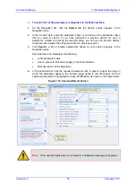
Page 887: ...00 1000 Base T Copper Support for T1 SHDSL ADSL2 and Optical Gigabit Ethernet LAN 4 ports 10 100 1000Base T and additional 8 10 100Base TX ports PoE Power Over Ethernet on all ports is optional Compliant to 802 3af 2003 with auto detection Up to 15 4W per port PoE management WiFi Optional WiFi Access Point support for 802 11 a b g n OSN Server Platform Optional Single Chassis Integration Embedded ...

Page 888: ...ing Loop Start FXS FXO Caller ID polarity reversal distinctive ringing visual Message Waiting Indication Data Routing Optional DHCP PPPoE L2TP PPTP client towards WAN DHCP server towards LAN VLAN Layer 3 routing Internal layer 2 switching Static and dynamic routing RIP1 RIP2 OSPF BGP Control and Management Control Protocols SIP TCP SIP UDP SIP TLS and SIP MSCML IPv6 Supported Standalone Survivabil...

Page 889: ...Ping of Death 9 Properly formed request from unauthenticated source 9 DDoS attack 9 SYN flood Stateful packet inspection firewall DMZ Host Port Triggering Packet Filtering Application Layer Gateway Hardware Specifications Power Supply Single universal power supply 100 240V 1 5A 50 60 Hz Physical Dimensions 320mm x 345mm x 1U Regulatory Compliance Safety and EMC Standards UL60950 1 EN60950 1 CB cer...

Page 890: ...User s Manual Ver 6 2 www audiocodes com ...

Reviews: