background image

Hardware Installation Manual  

46  

Document #: LTRT-40881 


Mediant 1000B MSBR 


5.6.2 

Connecting the PSTN Fallback for E1/T1 

The device  supports a PSTN Fallback feature, whereby upon a power outage or IP 
connectivity problem (e.g., no ping), IP calls are re-routed  to the PSTN. This guarantees 
call continuity.  

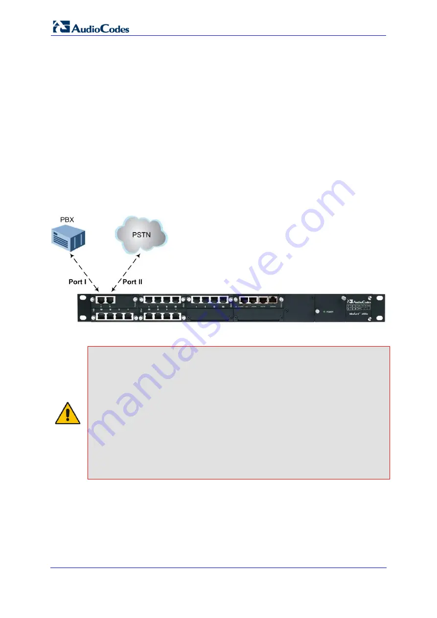
PSTN Fallback is supported if the device houses one or two E1/T1 ("TRUNKS") modules, 
where each module provides two or four spans. In the event of a PSTN fallback, the 
module's metallic relay switch automatically connects trunk Port 1 (

I

) to Port 2 (

II

), and / or 

trunk Port 3 (

III

) to Port 4 (

IIII

) of the same module. For example, if  a PBX trunk is 

connected to Port 1 and the PSTN network is connected to Port 2, when PSTN Fallback is 
activated, calls from the PBX are routed directly to the PSTN through Port 2. 


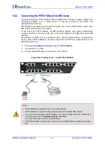
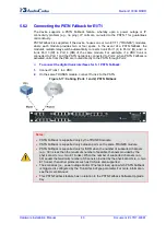
To connect the digital trunk interfaces for 1+1 PSTN Fallback: 

1. 

Connect Trunk 1 to a PBX. 

2. 

On the same TRUNKS module, connect Trunk 2 to the PSTN.  

Figure 


5-17: Cabling (Ports 1 and 2) PSTN Fallback 


Notes:  


PSTN Fallback is supported only by the TRUNKS module. 


PSTN Fallback is supported only between ports on the same TRUNKS module. 


PSTN Fallback is supported only for ISDN when the number of supported channels 
(e.g., 30) is less than the maximum number of possible channels provided by the 
physical ports (e.g., two E1 trunks). When the number of supported channels (e.g., 
60) equals the maximum number of channels provided by the physical ports (e.g., two 
E1 trunks), then other protocols such as CAS are also supported. 


The scenarios (i.e., power outage and/or IP network loss) upon which PSTN Fallback 
is triggered is configured by the TrunkLifeLineType parameter. For more information, 
see the 

User's Manual


This PSTN Fallback feature has no relation to the PSTN Fallback Software Upgrade 
Key. 


Summary of Contents for Mediant 1000B

Page 1: ...Hardware Installation Manual Mediant 1000B MSBR Multi Service Business Router SIP Protocol ...

Page 2: ......

Page 3: ...WAN SHDSL LED 24 3 2 7 Power Supply Module and LED Description 25 3 3 Rear Panel Description 26 4 Mounting the Device 27 4 1 Desktop Mounting 27 4 2 19 inch Rack Mounting 28 4 2 1 Mounting in a 19 inch Rack using a Pre Installed Shelf 28 4 2 2 Mounting in a 19 inch Rack using Front Mounting Brackets 29 4 2 3 Mounting in a 19 inch Rack using Rear Mounting Brackets 30 5 Cabling the Device 35 5 1 Gro...

Page 4: ...Rear Panel 54 6 1 5 1 Installing an AMC Module 54 6 1 5 2 Removing an AMC Module 54 6 1 6 Replacing I O Modules on the Front Panel Slots 55 A Open Solution Network Server Platform 57 A 1 OSN Server Offerings 57 A 2 OSN Server Modules Physical Description 57 A 2 1 OSN3 Module 58 A 2 1 1 Ports Description 58 A 2 1 2 LEDs Description 59 A 2 2 OSN4 Module 61 A 2 2 1 Ports Description 61 A 2 2 2 LEDs D...

Page 5: ...J 11 Connector Pinouts for Analog Lifeline 42 Figure 5 11 Cabling the Analog Lifeline 42 Figure 5 12 Connecting BRI Ports 43 Figure 5 13 RJ 45 Connector Pinouts for BRI 43 Figure 5 14 Cabling Ports 1 and 2 PSTN Fallback 44 Figure 5 15 RJ 48c Connector Pinouts for E1 T1 45 Figure 5 16 Cabling E1 T1 Trunk Ports 45 Figure 5 17 Cabling Ports 1 and 2 PSTN Fallback 46 Figure 5 18 Orderable RS 232 Cable ...

Page 6: ...net LED Description 24 Table 3 11 WAN SHDSL LED Description 24 Table 3 12 Power Supply Module LED Description 25 Table 3 13 Rear Panel Description 26 Table 5 1 RJ 45 Connector Pinouts for SHDSL 38 Table A 1 OSN Server Platforms 57 Table A 2 OSN3 Module Port Description 58 Table A 3 Gigabit Ethernet Interface RJ 45 Connector Pinouts 58 Table A 4 RS 232 Serial Cable Connector Pinouts 59 Table A 5 OS...

Page 7: ...ts reserved This document is subject to change without notice Date Published August 17 2016 Trademarks AudioCodes AC HD VoIP HD VoIP Sounds Better IPmedia Mediant MediaPack What s Inside Matters OSN SmartTAP VMAS VoIPerfect VoIPerfectHD Your Gateway To VoIP 3GX VocaNOM and CloudBond 365 are trademarks or registered trademarks of AudioCodes Limited All other products or trademarks are property of t...

Page 8: ...Ethernet port interface cabling must be routed only indoors and must not exit the building Warning The device is supplied as a sealed unit and must be installed and serviced only by qualified service personnel Warning Disconnect the device from the mains and Telephone Network Voltage TNV before servicing Caution Electrical Shock Do not open or disassemble this device The device carries high voltag...

Page 9: ... number of devices that may be connected to a line as determined by the total RENs contact the local telephone company For products approved after July 23 2001 the REN for this product is 0 01 4 Should the product cause harm to the telephone network the telephone company will notify you in advance that temporary discontinuance of service may be required If advance notice is not practical you will ...

Page 10: ...t operations or procedures that could affect the operation of the equipment If this happens the telephone company will provide advance notice in order for you to make necessary modifications to maintain uninterrupted service 5 If trouble is experienced with this equipment for repair or warranty information please contact AudioCodes Inc 27 World s Fair Drive Somerset NJ 08873 Tel 1 888 586 4743 Fax...

Page 11: ...nt 1000B MSBR 1 Introduction This document provides a hardware description of the Mediant 1000B MSBR hereafter referred to as device and step by step procedures for cabling the device Note For information on configuring the device refer to the device s User s Manual ...

Page 12: ...Hardware Installation Manual 12 Document LTRT 40881 Mediant 1000B MSBR Reader s Notes ...

Page 13: ...s 2 Remove the chassis from the carton 3 Check that there is no equipment damage 4 Ensure that in addition to the chassis the package contains the following items One or two AC power cables depending on customer order Four anti slide bumpers for desktop installation Two meter RS 232 DB 9 adaptor cable for direct serial connection to PC 5 Check retain and process any documents If there are any dama...

Page 14: ...Hardware Installation Manual 14 Document LTRT 40881 Mediant 1000B MSBR Reader s Notes ...

Page 15: ... media processing such as announcements and conferencing Ethernet and WAN interfaces provided on the CRMX module 3 x Ethernet LAN 10 100 1000Base T ports 1 x WAN port available in one of the following configurations depending on CRMX module type CRMX C RJ 45 port 4 twisted pair copper cabling providing 1 Gigabit Ethernet GbE interface CRMX S 1000Base SX optical fiber port multi mode fiber CRMS L 1...

Page 16: ...n the table below Table 3 1 Physical Dimensions Item Description Enclosure 1U chassis Dimensions H x W x D 1U x 440 mm 17 in x 350 mm 14 in Weight Approx 52 kg 115 lbs without modules each module is approx 110 g 0 114 lbs Environmental Operational 0 to 40 C 32 to 104 F Storage 20 to 70 C 4 to 158 F Relative Humidity 10 to 85 non condensing ...

Page 17: ...dule see Section 3 2 4 on page 21 for a description 2 MPM MPM module see Section 3 2 5 on page 22 for a description 3 CRMX CRMX module see Section 3 2 6 on page 23 for a description 4 This slot is currently not used and is covered by a blank panel In the next applicable release this slot is intended to host a LAN extension module for more information contact AudioCodes sales representative 5 Power...

Page 18: ...rfaces and therefore the device can support up to 24 FXS interfaces i e 6 modules x 4 ports Note The FXS modules support both loop and ground start signaling 3 2 1 1 Port Description Each FXS module provides up to four analog RJ 11 ports The ports are labeled I II III and IIII Figure 3 2 FXS Module 3 2 1 2 LED Description Each FXS port provides a LED for indicating operating status as described in...

Page 19: ...oth loop and ground start signaling but only supports indoor protection To enable ground start signaling use the ini file parameter GroundKeyDetection refer to the device s User s Manual 3 2 2 1 Port Description Each FXO module provides up to four analog RJ 11 ports The ports are labeled I II III and IIII Figure 3 3 FXO Module 3 2 2 2 LED Description Each FXO port provides a LED for indicating ope...

Page 20: ...device can support up to 20 BRI interfaces i e 5 modules x 4 ports 3 2 3 1 Port Description Each BRI module provides up to four analog RJ 45 ports The ports are labeled I II III and IIII Figure 3 4 BRI Module 3 2 3 2 LED Description Each BRI port provides a LED for indicating operating status as described in the table below Table 3 5 BRI Module LED Description Color State Description Green On Phys...

Page 21: ...eled I II III and IIII Figure 3 5 TRUNKS Module 3 2 4 2 LED Description Each Trunk port provides a LED for indicating operating status as described in the table below Table 3 6 E1 T1 PRI TRUNKS Module LED Description Color State Description Green On Trunk is synchronized normal operation Red On Loss due to any of the following signals LOS Loss of Signal LOF Loss of Frame AIS Alarm Indication Signa...

Page 22: ...table below Table 3 7 MPM LED Description Color Description Green Following insertion of the MPM into the slot and an automatic hardware compatibility check the LED lights up green to indicate 1 that the general status of the MPM is OK and 2 that the device supports the module Red If the LED lights up red following insertion of the MPM into the slot and the automatic hardware compatibility check i...

Page 23: ...t LAN ports for connecting computers and or switches O O RS 232 port for accessing the CLI A 9 pin DB adaptor cable is supplied Reset pinhole button for resetting the device and restoring the device to factory defaults This is done as follows With a paper clip or any other similar pointed object press and hold down the Reset button for at least 12 seconds but no longer than 25 seconds 0 0 WAN or S...

Page 24: ...ng table describes the LED for the WAN Ethernet port Table 3 10 WAN Ethernet LED Description LED Color LED State Description Green On WAN link established Flashing Data is being received or transmitted Off No WAN link Off No power received by the device 3 2 6 2 3 WAN SHDSL LED The following table describes the LED for the WAN SHDSL port Table 3 11 WAN SHDSL LED Description LED Color LED State Desc...

Page 25: ...each providing an AC power connector on the device s rear panel The dual power option provides the device with power redundancy Figure 3 8 Power Supply Module Table 3 12 Power Supply Module LED Description LED Color State Description POWER Green On Power supply is operating correctly Off Failure disruption in the AC supply or the power is currently not being supplied to the device through the AC p...

Page 26: ...el Description Item Label Description 1 Protective earthing screw 2 ESD Electrostatic Discharge ESD socket 3 100 240V 1A Dual AC Power Supply Entries 4 OSN3 OSN3 AMC module 5 HDMX Main hard disk drive HDD AMC module for OSN3 platform 6 HDMX Slot for second optional HDD for OSN3 platform 7 Unused and covered AMC module slots Notes The AMC chassis slots must only be installed with AMC modules that h...

Page 27: ...rs supplied to the underside of the device Once you have attached these bumpers simply place it on a desktop in the desired position To attach the anti slide rubber bumpers to the device 1 Flip the device over so that its underside faces up 2 Locate the four anti slide grooves on the underside one on each of the four corners Figure 4 1 Location of Grooves for Rubber Feet 3 Peel off the adhesive an...

Page 28: ...eration on the equipment is not compromised Mechanical Loading Mounting of the equipment in the rack should be such that a hazardous condition is not achieved due to uneven mechanical loading Circuit Overloading Consideration should be given to the connection of the equipment to the supply circuit and the effect that overloading of the circuits might have on over current protection and supply wiri...

Page 29: ... To mount the device in a 19 inch rack using front mounting brackets 1 With two people lift the chassis into the rack from the front of the rack 2 Hold the chassis for support while the second person positions the chassis so that the front mounting brackets are flush against the front rack posts and that the holes of the brackets align with the holes on the posts Note Make sure that the left and r...

Page 30: ...te orderable item The customer part number CPN for ordering this kit is M REAR RMK1 Warnings At least two people are required to mount the device in the 19 inch rack When attaching the device to the rack using the rear mounting brackets it is mandatory to also attach the front mounting brackets To allow extraction and insertion of modules on the rear panel make sure that the distance between the r...

Page 31: ...he rack See the figure below for correct orientation of the brackets when attaching them to the posts Figure 4 2 Rear Mounting Brackets Attached to Rear Rack Posts 3 Attach the flanges of the adjustable rear mounting brackets to the rear sides of the chassis using the six supplied screws three per bracket Figure 4 3 Attaching Rear Mounting Bracket Flange to Chassis Rear Side Mounting Holes 4 With ...

Page 32: ...s 6 Hold the chassis in position while the second person secures the rear mounting flanges to the rear mounting brackets Insert the supplied screw 6 32 x 5 16 inch from the inside of the rack through the flange s grid and into the screw hole on the rear mounting bracket Finger tighten the screw but make sure that the screw is not fully tightened and that the flange can move on the slide rails of t...

Page 33: ...ackets to the front posts by finger tightening 19 inch rack bolts not supplied to the rack posts Do this for both front mounting brackets left and right side 9 Tighten the bolts on the front mounting brackets 10 With a Philips screwdriver tighten the screw that secures the rear mounting flange to the rear mounting bracket Notes Make sure that all the mounting brackets are attached at the same leve...

Page 34: ...Hardware Installation Manual 34 Document LTRT 40881 Mediant 1000B MSBR Reader s Notes ...

Page 35: ...ng to a PC for serial communication see Section 5 7 on page 47 Connecting to power see Section 5 8 on page 49 5 1 Grounding the Device The procedure below describes how to ground the device Protective Earthing The equipment is classified as Class I EN 60950 and UL 60950 and must be earthed at all times using an equipment earthing conductor Finland Laite on liltettava suojamaadoituskoskettimilla va...

Page 36: ...n page 38 5 2 1 Gigabit Ethernet Copper Cabling The procedure below describes how to connect to the WAN through the 100 1000Base TX Gigabit Ethernet RJ 45 port provided on the CRMX C module An RJ 45 cable connector with the following pinouts is used Figure 5 2 RJ 45 Connector Pinouts for WAN Ethernet To connect to the WAN using the GbE port 1 Attach one end of a straight through RJ 45 Ethernet Cat...

Page 37: ...ot stare directly into the beam or into fiber optic terminations as this can damage your eyesight Avoid exposure to laser radiation by ensuring that you insert dust EMI plugs into SFP transceiver modules to which no cables are connected Laser radiation may be emitted from the aperture of the SFP transceiver modules when no cables are connected Excessive bending of the fiber optic cable can cause d...

Page 38: ...FM and ATM support Wetting current support on the CPE side according to G991 2 Supports both Central Office CO and CPE wetting current on CO excluded TC PAM 16 32 Line Code An RJ 45 cable connector with the following pinouts is used Table 5 1 RJ 45 Connector Pinouts for SHDSL Pin Function 4 CH0 TIP 5 CH0 RING 1 CH1 TIP 2 CH1 RING 3 CH2 TIP 6 CH2 RING 7 CH3 TIP 8 CH3 RING Warning Do NOT use an RJ 1...

Page 39: ... Warning Ethernet port interface cabling must be routed only indoors and must not exit the building An RJ 45 cable connector with the following pinouts is used Figure 5 6 RJ 45 Connector Pinouts for LAN To connect to the LAN 1 Using a straight through RJ 45 Ethernet Cat 6 or Cat 5e two pair Category 5 UTP cable connect the CRMX module s LAN port s labeled I II and III to the LAN Figure 5 7 Connect...

Page 40: ...it and thus must be installed only indoors FXS port interface cabling must be routed only indoors and must not exit the building Make sure that FXS ports are connected to the appropriate external devices otherwise damage to the device may occur The FXS ports are considered as TNV 2 Note This section is applicable only if your device is installed with an FXS module An RJ 11 cable connector with the...

Page 41: ...STN Ensure that FXO ports are connected to the appropriate external devices otherwise damage to the device may occur FXO ports are considered as TNV 3 Note This section is applicable only if your device is installed with an FXO module An RJ 11 cable connector with the following pinouts is used Figure 5 9 RJ 11 Connector Pinouts for FXO To connect to FXO interfaces Using an RJ 11 connector connect ...

Page 42: ...cts pins 1 and 4 to another source of an FXS port and pins 2 and 3 to the POTS phone as shown in the figure below Figure 5 10 RJ 11 Connector Pinouts for Analog Lifeline To cable the analog Lifeline 1 Connect the Lifeline Splitter supplied to Port I on an FXS module 2 Connect the Lifeline POTS phone to Port A on the Lifeline Splitter 3 Connect an analog PSTN line to Port B on the Lifeline Splitter...

Page 43: ...t to BRI lines 1 Connect the BRI cable to the device s BRI RJ 45 port Figure 5 12 Connecting BRI Ports 2 Connect the other end of the cable to your ISDN telephone or PBX PSTN switch A BRI port can be configured either as TE Termination Equipment user side or NT Network Termination network side The connector pinouts vary according to the configuration as shown below Figure 5 13 RJ 45 Connector Pino...

Page 44: ...t 4 IIII of the same BRI module For example if a PBX trunk is connected to Port 1 and the PSTN network is connected to Port 2 when PSTN Fallback is activated calls from the PBX are routed directly to the PSTN through Port 2 To connect the BRI line interfaces for 1 1 PSTN Fallback 1 Connect line 1 to a PBX 2 On the same BRI module connect line 2 to the PSTN Figure 5 14 Cabling Ports 1 and 2 PSTN Fa...

Page 45: ... 26 AWG min wire to connect T1 or E1 ports to the PSTN Note This section is applicable only if your device is installed with a TRUNKS module An RJ 48c trunk cable connector with the following pinouts is used Figure 5 15 RJ 48c Connector Pinouts for E1 T1 To connect to E1 T1l trunks 1 Connect the E1 T1 trunk cables to the ports on the device s TRUNKS module s Figure 5 16 Cabling E1 T1 Trunk Ports 2...

Page 46: ...ough Port 2 To connect the digital trunk interfaces for 1 1 PSTN Fallback 1 Connect Trunk 1 to a PBX 2 On the same TRUNKS module connect Trunk 2 to the PSTN Figure 5 17 Cabling Ports 1 and 2 PSTN Fallback Notes PSTN Fallback is supported only by the TRUNKS module PSTN Fallback is supported only between ports on the same TRUNKS module PSTN Fallback is supported only for ISDN when the number of supp...

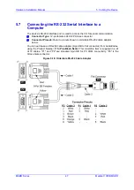
Page 47: ...ype 12 pin female LX40 12P Hirose connector Connector Pinouts Refer to pinouts shown in orderable RS 232 cable adaptor below You can purchase an RS 232 cable adapter 9 pin DB to flat connector from AudioCodes using the Product Number P N PicoBlade Serial This orderable item is supplied in a kit of 10 cables P1 and P2 are standard 9 pin DB for PC COM connectivity P3 is the Hirose male connector Fig...

Page 48: ...N Withstand Voltage AC 250V 2mA for one minute Continuity test 100 RoHS Note All materials composing this item should comply with the requirements of directive 2002 95 ec on the restriction of the use of certain hazardous substances in electrical and electronic equipment UL Note Cable components according to UL standard To connect the serial interface port to a computer 1 Connect the flat connecto...

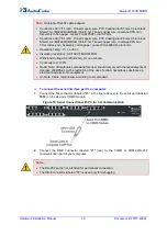
Page 49: ... power connector on the device s rear panel The dual power option provides the device with power redundancy If both power units are used for load sharing failure protection redundancy ensure that you connect each power supply unit to a different AC supply circuit For installing the Power Supply modules in the chassis see Section 6 1 3 on page 53 The two AC power sources must have the same ground p...

Page 50: ...ce s rear panel connect the left active 100 240V 50 60 Hz power socket to a standard electrical outlet using the supplied AC power cord Figure 20 Connecting to Power When the device receives powers the POWER LED on the front panel of the Power Supply module is lit green If the LED is off a power supply problem may be present ...

Page 51: ...upied module slots are covered with blank panels This prevents dust from entering the chassis and ensures even air flow within the chassis for cooling 6 1 1 Module Slot Assignment The device s front panel chassis provides slots numbered as shown in the figure below for housing the main input output I O interface modules i e TRUNKS BRI FXS FXO MPM and CRMX Figure 6 1 Module Chassis Slot Assignment ...

Page 52: ...40 channels as well thereby providing a total of 100 media channels for conferencing For applications other than conferencing e g SBC IP to IP routing and announcements the MPM modules can be housed in slots 3 4 and 5 Each module provides 40 channels thereby providing a total of 120 channels 60 for IP to IP call sessions The device can acquire additional media channel resources for SBC IP to IP ro...

Page 53: ...dules into Previously Empty Front Panel Slots The procedure below describes how to install modules to previously empty slots in the device s chassis Warning Ensure that you power down the device before installing a module to a previously empty slot To install a module into a previously empty slot 1 Power off the device 2 On the device s front panel using a Phillips screwdriver remove the black met...

Page 54: ...s how to install an AMC module into the chassis slot To install an AMC module 1 Carefully insert the module into the slot until it makes contact with the AMC card edge connector located on the backplane 2 Connect all external interfacing cables to the module as required 3 Using the module handle engage the module with the chassis backplane 4 When the handle is locked the module is engaged and the ...

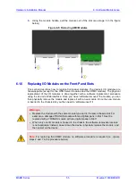
Page 55: ...nterface Once you have software removed the module you can then physically remove the module and replace it with a new module Once the new module is inserted in the chassis slot you then need to software insert it Warnings Replace the module with the same module type and in the same chassis slot For example a damaged TRUNKS module with two digital spans in Slot 1 must be replaced with a TRUNKS mod...

Page 56: ...ientation of the module as follows Top row slots ensure that the module is orientated such that the port number labels are located at the bottom of the module s front panel This module orientation is considered as facing up Bottom row slots ensure that the module is orientated such that the port number labels are located at the top of the module s front panel This module orientation is considered ...

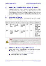
Page 57: ...rver Platforms OSN Platform CPU Memory Storage Bus Chipset Cache Interfaces OSN3 Intel Core 2 Duo 1 5 GHz 2 or 4 GB DDR2 with ECC Up to 2 hard drives HDD or SSD 64 bit 2 MB External Gigabit Ethernet Internal Gigabit Ethernet USB 2 0 RS 232 COM OSN4 Intel Core i7 3555LE Dual Core 2 5 GHz 8 GB DDR3 with ECC Up to 2 hard drives HDD or SSD 64 bit 4 MB Two external Gigabit Ethernet Internal Gigabit Eth...

Page 58: ...erial interface COM1 2 RJ 45 port for Gigabit Ethernet The interface provides automatic detection and switching between 10Base T 100Base TX and 1000Base T data transmission Auto Negotiation Auto wire switching for crossed cables is also supported Auto MDI X 3 USB 2 0 port 4 Handle for inserting and extraction module from slot The RJ 45 connector pinouts for Gigabit Ethernet interface are listed in...

Page 59: ... for RS 232 interface are listed in the table below Table A 4 RS 232 Serial Cable Connector Pinouts RJ 45 Pin DB 9 Pin 1 8 2 6 3 2 4 5 5 5 6 3 7 4 8 7 A 2 1 2 LEDs Description The OSN3 module LEDs are shown in the figure below and described in the subsequent table Figure A 3 OSN3 Module LEDs Table A 5 OSN3 Module LEDs Description Item Label Color State Description 1 Green Flashing Hardware normal ...

Page 60: ...Off Normal operation 5 0 Red On When lit up during boot up indicates a BIOS boot failure Flashing Processor over temperature above 125 C and as a result OSN3 shuts down if LEDs 1 2 and 3 are also flashing Off Normal operation 6 Blue Flashing Module undergoing shutdown sequence when module pulled out to first extraction position On Module shutdown sequence complete and the module can be extracted f...

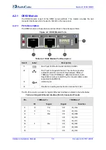
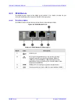
Page 61: ... shown below and described in the subsequent table Figure A 4 OSN4 Module Ports Table A 6 OSN4 Module Port Description Item Label Description 1 USB 2 0 port 2 RJ 45 port for Gigabit Ethernet The interface provides automatic detection and switching between 10Base T 100Base TX and 1000Base T data transmission Auto Negotiation Auto wire switching for crossed cables is also supported Auto MDI X 3 HDMI...

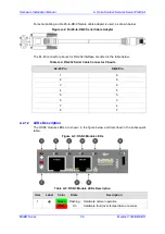
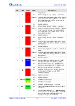
Page 62: ...re shown in the figure below and described in the subsequent table Figure A 5 OSN4 Module LEDs Table A 8 OSN4 Module LEDs Description Item Color State Description 1 Green Flashing Firmware BIOS application active payload x86 in sleep Solid Firmware BIOS application active payload x86 active 2 Red On Out of service indicator due to hardware failure Off Normal operation 3 Green Solid Valid Ethernet ...

Page 63: ...hassis slot A 2 3 HDMX Module The HDMX module provides the hard disk drive functionality for the OSN platform providing storage capacity The capacity depends on the OSN platform see Section A 1 on page 57 The HDMX module is housed in Slot 1 on the rear panel Notes For additional storage capacity per HDMX module contact your AudioCodes sales representative The OSN platform can optionally be ordered...

Page 64: ... To install operating system on OSN3 1 Connect the RS 232 interface port RJ 45 located on the OSN3 module to a PC using the RS 232 cable supplied Figure A 7 Cabling OSN3 Module for Installing Linux 2 Start a terminal application e g HyperTerminal on your PC and create a new connection with the following settings Baudrate 115200 bits per second Data Bits 8 Parity None Stop Bits 1 Flow Control None ...

Page 65: ... then connect the USB hub to the following computer peripherals Mouse Keyboard USB storage device containing the Linux distribution installation files disk on key or external CD ROM or DVD ROM drive 2 Connect the HDMI port located on the OSN4 module to your monitor Figure A 8 Cabling OSN4 Module for Installing Linux 3 Power up the device the OSN server boots up from the USB storage device and the ...

Page 66: ...ic IP address 10 1 10 12 is no longer applicable This is because the module becomes a DHCP client and acquires a different IP address To configure a specific IP address you need to use a serial console as described below To manually configure an IP address for the scenario described in the note above 1 Connect the OSN3 serial interface port to a PC console using the RJ 45 to DB 9 cable adapter see...

Page 67: ...Connection to the server s IP network interface The server connects initially to the IP network through the LAN port of the OSN3 module To connect to OSN3 through Remote Desktop Connection 1 Connect the Ethernet LAN port of the OSN3 module to the LAN network by performing one of the following Remote PC connection Using a straight through cable connect the LAN port to a switch that is connected to ...

Page 68: ...and then click Remote Desktop Connection Figure A 11 Entering IP Address in Remote Desktop Connection 4 In the Computer field enter the OSN server s default IP address i e 10 1 10 12 5 Click Connect Figure A 12 Entering User Name and Password in Remote Desktop Connection 6 Enter the OSN server s default username administrator and password 123456 7 Click OK Remote Desktop Connection connects you to...

Page 69: ...1V1 Dual Trunks w life line module C08 FASB00399 M1K TMX 1A1V1 Single trunks w life line module C08 FASB00510 M1K OMX S 4 Indoor Ports With GS Rev A1 C05 FASB00511 M1K CFMX 1 Conference Module Rev A1v1 C06 FASB00520 M1K OMX S 4 Outdoor Ports W O GS Rev A1 C04 FASB00582 M1K BMX 4A1 C03 GTPM00046 M1K VM 2FXS P03 GTPM00050 M1K VM 1SPAN P03 GTPM00052 M1K VM 2SPAN P03 GTPM00051 M1K VM 4SPAN P03 GTPM000...

Page 70: ...Hardware Installation Manual www audiocodes com ...

Reviews: