
2
■
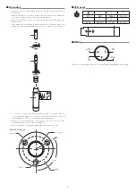
Assembly
1.
• Insert the gooseneck assembly (c) while rotating it into the XLR power
module (d).
• Tighten until it does not rotate, and use the hex wrench (f) to tighten the
set screw (e) and set the gooseneck assembly in place.
• Connect the capsule (b) to the gooseneck assembly, and attach the
windscreen (a).
* If the parts are not sufficiently tightened together, problems may occur
such as the LED not lighting up to the set color or sound is not output.
a
b
c
d
e
f
2.
• If you are using the AT8474
(optional)
, make mounting reference
holes (with a
diameter of 1.5 mm(X) on the circumference of a circle
with a
diameter of 40 mm (1.6")) in the mounting surface.
• Make a hole with a diameter of 25.4 mm (1") in the center (Y) of the
mounting surface for the XLR power module.
• The outer diameter of the mounting surface is 52.4 mm (2.1") (Z).
120°
Y
Z
φ
52.4
3-
φ
1.5
φ
40.0
φ
25.4
X
AT8474
(Optional)
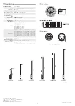
■
LED color
1
2
3
OFF
RED
GREEN
YELLOW
4
5
6
7
BLUE
MAGENTA
CYAN
WHITE
■
Wiring
1
2
3
PIN2
(Hot)
PIN1
(LED control)
CASE
(Ground)
PIN3
(Cold)
LED control only available with ATUC series products and AT8699R desk stand


