Audio Pole DSP 24 User Manual Download Page 13


6-

USER INTERFACE SELECTION 

The DSP 24 can be programmed by a computer. There is an USB port (cable supplied) and a RS485 port (XLR). The USB 
port enables the connection between one PC computer and one single DSP24. 
The RS485 enables the communication between one PC computer and a network including several DSP24. 
 

Selection of the interface: 

Press 

UTILITY

 and use 

NAV/PM1

 to display «System Utilities» 

Press 

ENTER

 and use 

NAV/PM1

 to display «Interface Setup» 

Press 

ENTER

 and use 

PM2

 or 

PM3 

to select «Source: USB» or «Source: RS485. The current status is indicated with 

an asterisk on the right corner of the screen. 

Press 

ENTER 


7-

RESET PROCEDURE 

If the DSP 24 has been locked with a password and the password is lost or forgotten the device cannot be unlocked with the 

programmed parameters anymore. 
The device needs to be reset to the factory parameters status. In this case all parameters and presets will be definitively 
deleted and lost. 
 
Reset of the device: 

Switch off the DSP 24. 

Press 

ENTER

ESC

 and 

UTILITY

 simultaneously by switching the power on. 

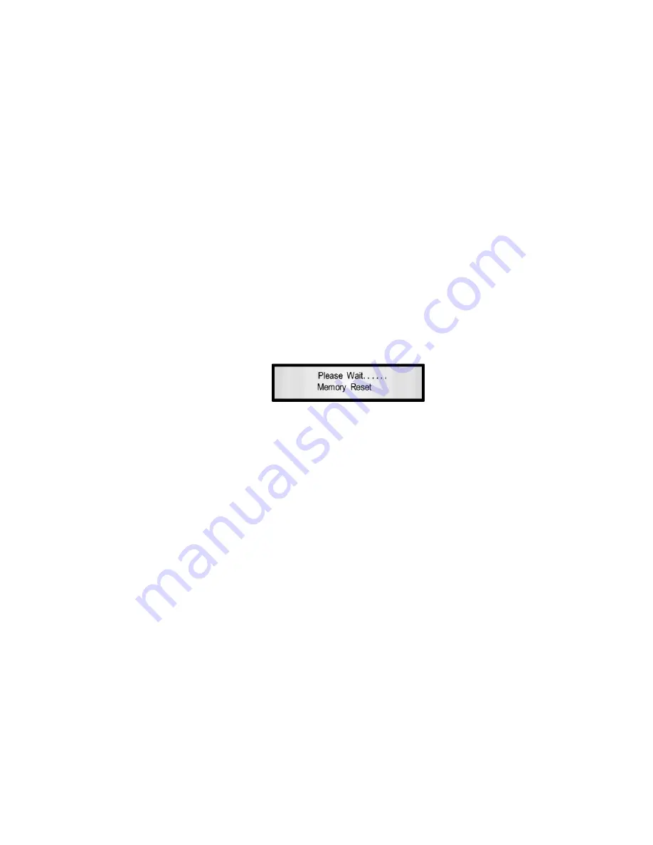
The display indicates : 


Release the button and wait for the end of the procedure.


USER’S MANUAL DSP 24 


page 10 

III- TECHNICAL SPECIFICATIONS 


Analog inputs: 


channel A, B, balanced XLR 

Maximum input level: 


+20 dBu 

Analog outputs:    


channel 1-4, balanced XLR 

Maximum output level: 


+20 dBu 

DSP: 


SAM3716, 24 bits 

A/D converters: 


AKM5392, 24 bits 

D/A converters: 


AKM4396, 24 bits 

Sampling frequency: 


48k Hz 

Stereo digital input S-PDIF:    


compatible with 32 kHz, 44.1 kHz and 48 kHz sampling rate 

S/N ratio:  


110 dBA 

THD + N:  


0.005% 

Frequency response (bypass):  


20 Hz-20 kHz (+/-1dB) 

Power supply:  


Switching 

Interface:  


USB - RS485 


Summary of Contents for DSP 24

Page 1: ...Speaker Management Processor DSP 24 USER S MANUAL...

Page 2: ...o the ground don t remove the ground wiring of the power cord connector HUMIDITY Do not expose the unit to rain or moisture and do not place container containing a liquid that might tip over Do not ha...

Page 3: ...r page 4 C PRESETS MANAGEMENT page 5 1 Presets save page 5 2 Presets recall page 6 3 Presets delete page 6 D LOCK page 7 1 Simple lock page 7 2 Lock with password page 7 3 Display lock page 8 II APPEN...

Page 4: ...ds see paragraph B 2 below B PARAMETERS EDITING 1 INPUTS The signal path for every input is as follow Press quick push the button 7 of the input the blue Led lights NOTE It is possible to adjust two i...

Page 5: ...lve 6 or 12dB or 0 05 and 3 0 Octave with PM2 Variable level between 15 and 15dB with PM3 MOVE TO EQ 2 A without EQ 1 modification press NAV PM1 B after EQ 1 modification press ESC then press NAV PM1...

Page 6: ...TER A without having changed the gain press NAV PM1 B after the gain change press ESC and press NAV PM1 LIMITER Press ENTER then adjust the parameters Attack time from 5 to 200ms with NAV PM1 Release...

Page 7: ...LPF press NAV PM1 B after the LPF change press ESC and press NAV PM1 The DSP 24 features a 7 band EQ on every output EQ 1 to EQ 7 EQ 1 Press ENTER then adjust the parameters idem EQ 5 Variable frequen...

Page 8: ...ber the display indicates To clear and overwrite an existing preset press ENTER then the display indicates Confirm by pressing ENTER and the display indicates Use NAV PM1 to browse and PM2 and PM3 to...

Page 9: ...preset choice by pressing ENTER the display indicates NOTE At any time you can cancel the procedure by pressing ESC 3 PRESETS DELETE Press ENTER and use NAV PM1 to display Press ENTER and use NAV PM1...

Page 10: ...asily changed In case of fixed installation or for renting business the procedure could be not applicable in this case see the procedure described in paragraph D2 b It is possible to have all the para...

Page 11: ...DEVICE Follow the instructions as described on Simple Lock It is possible to make all parameters invisibles see paragraph 3 At this stage the device is fully locked none of the button is active except...

Page 12: ...on the right corner of the screen Press ENTER 3 UNIT FOR THE DELAY The delay adjustment can be specified in Distance meters or in Time milliseconds Selection of the unit Press UTILITY and use NAV PM1...

Page 13: ...otten the device cannot be unlocked with the programmed parameters anymore The device needs to be reset to the factory parameters status In this case all parameters and presets will be definitively de...

Page 14: ...s for a period of two years from the date of purchase by the first user Conditions 1 The unit has been installed and implemented by observing the safety instructions in this operating manual 2 The dev...

Reviews: