background image

Audio International, Inc.


                  VCP-010-06(-07)-x Installation & Operation Manual 


Document # 540236, Rev IR, 11/2002  


Page 14 of 21 

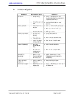
8.2   Troubleshooting Chart 


Problem Possible 

Cause 

Solution 

No power 

Ø 

Faulty wiring 


Ø 

Circuit breaker not 
‘ON’ 

• 

28 VDC power and 
audio/video input is present and 
recheck connections 


• 

Turn circuit breaker to ‘ON’ 
position 


Unclear picture 

Ø 

Video heads may 
be dirty 


Ø 

Incorrect Format 


• 

Use a commercial head cleaner 


• 

Replace videocassette tape 


• 

Change Format 

Video not present 

Ø 

Cassette not 
loaded 


Ø 

Tape defective 


Ø 

Video connector 
not operational 


• 

Load videocassette 


• 

Replace videocassette tape 


• 

Reconnect or repair cable 


Audio not present 

Ø 

Defective 
videocassette 
tape 


Ø 

Power/Audio 
connector not 
operational 


• 

Replace videocassette 


• 

Reconnect or repair cable 


Buttons not 
operating 

Ø 

Moisture may 
have condensed 
inside the unit 

• 

Allow unit to warm to room 
temperature and moisture to 
evaporate 


Tape cannot be 
inserted 

Ø 

Foreign object in 
tape slot 


• 

Remove foreign object 

Unit does not eject 

Ø 

EJECT button not 
functioning 


• 

28 VDC power and check 
connections 


Summary of Contents for VCP-010-06-1 VCP-010-06-2

Page 1: ...00 Industry Drive North Little Rock AR 72117 Phone 501 955 2929 Fax 501 955 2988 www audiointl com Installation and Operation Manual VCP 010 06 07 x Multi Standard Video Cassette Player Document 54023...

Page 2: ...Revision Revision Date Table of Illustrations Section Subsection Description Page I 6 2 Typical Application 6 7 II 9 1 Reference Drawings VCP 010 06 x 15 16 II 9 2 Reference Drawings VCP 010 07 x 17...

Page 3: ...al Equipment 5 5 0 Technical Specifications 5 6 0 Application 5 II INSTALLATION 8 1 0 Prior to Installation 8 2 0 Unpacking and Inspection 8 3 0 Cautions Warnings 9 4 0 Wiring Requirements 10 5 0 Phys...

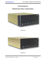
Page 4: ...Audio International Inc VCP 010 06 07 x Installation Operation Manual Document 540236 Rev IR 11 2002 Page 3 of 21 VCP 010 06 07 x Multi Standard Video Cassette Player VCP 010 06 x VCP 010 07 x...

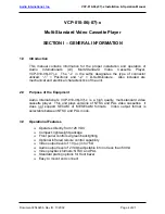
Page 5: ...cal characteristics of the unit 2 0 Purpose of the Equipment Audio International s VCP 010 06 07 x is a high quality multi standard video cassette player This unit plays versions of NTSC and PAL video...

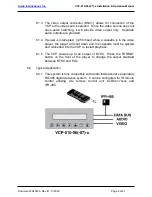
Page 6: ...uction 6 1 1 The VCP 010 06 07 x is a high quality multi standard video cassette player This unit plays versions of NTSC and PAL videocassettes The video output format is selectable between NTSC and P...

Page 7: ...s interrupted 250 msec while a cassette is in the video player the player will shut down and the cassette must be ejected and reinserted into the VCP to restart playback 6 1 5 The VCP powers up to an...

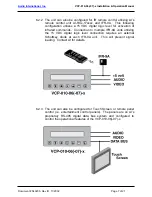
Page 8: ...level for activation of infrared commands Connection to multiple IFR 9A units utilizing the 5 VDC digital logic level connection requires an external Schottkey diode at each IFR 9A unit This will prev...

Page 9: ...g conditions as to the unit location and type of installation 1 3 Mounting screws are required to secure the unit Refer to Section II 9 0 for mounting hole diameters and configurations 1 4 All headpho...

Page 10: ...or ground is applied to the wrong points 3 2 DO NOT connect or disconnect the unit while power is applied 3 3 DO NOT remove any factory installed screws Damage to the unit may result and void any warr...

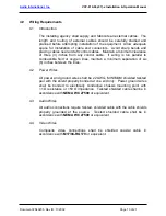
Page 11: ...parallel to combustible fluid or oxygen lines maintain a minimum separation of six 6 inches between the lines 4 2 Power Wires All power and ground wires shall be 22 AWG MINIMUM shielded twisted pair w...

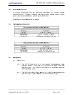
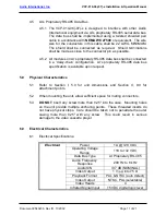
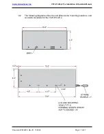
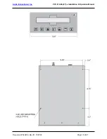
Page 12: ...pecification is available upon request 5 0 Physical Characteristics 5 1 Refer to Section I 5 0 for unit dimensions and Section II 9 0 for attachment points 5 2 When mounting the unit allow sufficient...

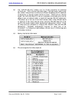
Page 13: ...evices when using the RS 485 data bus to be used in the same system while maintaining independent control Three 3 strap pins are available to configure the infrared codes and RS 485 addressing Standar...

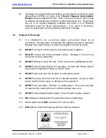
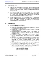
Page 14: ...ooting Procedures Check that 28 VDC power is applied to the proper pins on the unit Use a voltmeter to verify correct level Reset the unit by removing power from it for at least one 1 minute and then...

Page 15: ...lace videocassette tape Change Format Video not present Cassette not loaded Tape defective Video connector not operational Load videocassette Replace videocassette tape Reconnect or repair cable Audio...

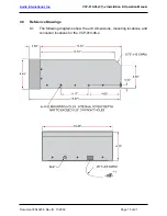
Page 16: ...010 06 07 x Installation Operation Manual Document 540236 Rev IR 11 2002 Page 15 of 21 9 0 Reference Drawings 9 1 The following diagrams show the unit dimensions mounting locations and connector loca...

Page 17: ...Audio International Inc VCP 010 06 07 x Installation Operation Manual Document 540236 Rev IR 11 2002 Page 16 of 21...

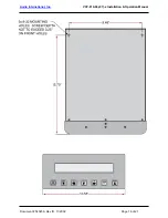
Page 18: ...onal Inc VCP 010 06 07 x Installation Operation Manual Document 540236 Rev IR 11 2002 Page 17 of 21 9 2 The following diagrams show the unit dimensions mounting locations and connector locations for t...

Page 19: ...Audio International Inc VCP 010 06 07 x Installation Operation Manual Document 540236 Rev IR 11 2002 Page 18 of 21...

Page 20: ...frared inputs or eight 8 of the same devices when using the RS 485 data bus to be used in the same system while maintaining independent control Three 3 strap pins are available to configure the infrar...

Page 21: ...into the Tape Slot 2 1 Gently insert a videocassette tape into the cassette tape slot Apply slight forward pressure to the side edge of the tape The VCP 010 06 07 x will gently pull the tape into the...

Page 22: ...f the videocassette tape 3 4 Play Button Press the PLAY button to begin videocassette tape viewing Pressing PLAY twice in succession activates double speed play 3 5 Fast Forward Button While the tape...

Reviews: