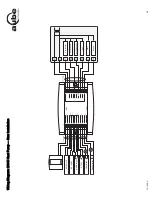
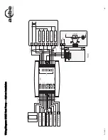
Aube Technologies CT280-3H3C Installation Manual Download Page 14

T

H

146-P

-U 


 6

/8

Schéma de br

anchement : ther

mopom

pe 3H

2C

 — i

nstall

ation «add-on» (ins

tall

ati

on m

odif

iée)

Fou

rn

a

ise

Th

ermo

stat


ventila

teur

fau

t

D

égi

vr

age

V

a

lve d

’in

versi

on

Comp

re

sseu

r 1

Comp

re

sseu

r 2

A

C

146-4

1

0

A

C

144-

03

Humidi

ficat

eur

Déshumid

ifi

ca

teu

r

CT

2

41

Bi

-éne

rgie

Summary of Contents for CT280-3H3C

Page 1: ...ule Install the control module near the heating cooling system away from any heat source Install the console in a central location Avoid locations with air drafts e g top of staircase or air outlet or...

Page 2: ...ed for add on installations only It is not needed if the heat pump is not connected to the controller terminal WW Install the sensor on the side of the plenum and position it such that its aperture fa...

Page 3: ...nace the auxiliary heat source is installed at the same time as the heat pump In this type of installation the indoor coils are located upstream of the auxiliary heat When the controller is configured...

Page 4: ...ry heat 2 24 Vac 1 A W3 O B Reversing valve 24 Vac 1 A G Fan 24 Vac 1A L Fault 24 Vac 5 mA WW Defrost 24 Vac 5 mA NOTE Requires a dry contact do not connect to a solid state relay such as a triac NC N...

Page 5: ...TH146 P U 5 8 Wiring Diagram 2H1C Heat Pump New Installation AC146 410 AC144 03 CT241 Humidifier Dehumidifier Compressor Auxiliary Heat Reversing Valve Fan Fault Defrost Dual Energy...

Page 6: ...TH146 P U 6 8 Wiring Diagram 3H2C Heat Pump Add on Installation AC146 410 AC144 03 CT241 Fault Defrost Reversing Valve Compressor 1 Compressor 2 Furnace Fan Limit Humidifier Dehumidifier Dual Energy...

Page 7: ...TH146 P U 7 8 Wiring Diagram 3H2C HVAC AC146 410 AC144 03 CT241 Cooling Unit 1 Cooling Unit 2 Heating Unit 1 Heating Unit 2 Fan Heating Unit 3 Humidifier Dehumidifier...

Page 8: ...on 4 6 NOTE The function is disabled if HLMT is set above its maximum 12 Cycles per hour 4 2 to 6 Select the number of heating cooling cycles per hour For optimal heating control use the setting that...

Page 9: ...ule Installer le module de contr le pr s du syst me de chauffage et climatisation loin des sources de chaleur Installer la console un endroit central viter les endroits o il y a des courants d air ex...

Page 10: ...u pl num et la positionner de sorte que l ouverture de lecture soit face au courant d air Raccorder la sonde aux bornes PS et CS du contr leur aucune polarit Pour plus d information se r f rer aux ins...

Page 11: ...mont du chauffage d appoint Lorsque le contr leur est configur pour une nouvelle installation la thermopompe et le chauffage d appoint peuvent fonctionner en m me temps Le d lai d activation est le te...

Page 12: ...ca 1 A W3 O B Valve d inversion 24 Vca 1 A G Ventilateur soufflerie 24 Vca 1A L D faut 24 Vca 5 mA WW D givrage 24 Vca 5 mA NOTA Exige un contact sec ne pas relier un relais semi conducteur tel un tri...

Page 13: ...8 Sch ma de branchement thermopompe 2H1C nouvelle installation Compresseur Valve d inversion Ventilateur D faut D givrage Chauffage d appoint AC146 410 AC144 03 Humidificateur D shumidificateur CT241...

Page 14: ...hement thermopompe 3H2C installation add on installation modifi e Fournaise Thermostat ventilateur D faut D givrage Valve d inversion Compresseur 1 Compresseur 2 AC146 410 AC144 03 Humidificateur D sh...

Page 15: ...TH146 P U 7 8 Sch ma de branchement CVAC 3H2C Refroidissement 1 Chauffage 1 Chauffage 2 Ventilateur Chauffage 3 AC146 410 AC144 03 Humidificateur D shumidificateur CT241 Refroidissement 2...

Page 16: ...ctiv e lorsque HLMT est plac au dessus du maximum 12 Cycles par heure 4 2 6 Permet de s lectionner le nombre de cycles par heure Pour un contr le optimal du chauffage choisir le r glage qui correspond...

Reviews: