


CHAPTER 1: SYSTEM OVERVIEW
VersAtive
®
Pro Mondo – Hardware Interface Manual
1-3
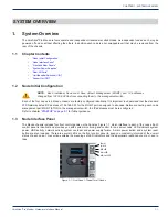
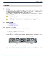
1.5 System Power Supplies
Each Mondo chassis includes a high-efficiency power supply, Figure 1-4, rated at 1620 Watts, and optionally, one similar
redundant backup power supply. In the unlikely event your power supply fails, replacement is simple and can be accomplished
without tools.
The power supply is used to provide the power for all four Nodes. Each Node however, can be shut down independently of the
other with the power button on its own control panel.
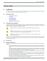
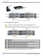
1.6 Rear I/O Ports
Figure 1-5 for locations of the ports. This layout is typical of the four independent nodes.
1. IPMI Dedicated LAN
2. USB Port 0
3. USB Port 1
4. MGMT (ETH0)
5. ETH1
6. (Not Used)
7.
VGA
8. UID Switch/L
9. ETH2
10. ETH3
11. ETH4
12. ETH5
1.7
Unit Identifier Switches (UID)
Two Unit Identifier (UID) Switch/LED Indicators are available on each node. The Front Panel UID Switch/LED is located at the
control panel adjacent each node, see
. The Rear UID Switch is located next to the VGA Connector of each node,
. When the user presses a UID switch on the front panel or back panel, both rear and front UID LED Indicators
will be turned on. Press the UID switch again to turn off both LED Indicators. These UID Indicators provide easy identification
of a node in a large rack installation that may be in need of service. Note: UID LED is supported by the physical switch or the
Baseboard Management Controller (BMC) which is a function related to IPMI. When it is controlled by the physical switch, it
will stay on solid. When it is controlled by the BMC, it will blink.
Power Indicator
Latch Lever
Figure 1-4: Redundant Power Supplies
Figure 1-5: Rear Panel Node Ports - Typical for all Nodes


