


HFC Enhance
®
– QFHPN High Power Optical Node with AGC – Installation & Operation Manual
2-1
CHAPTER 2: INSTALLATION AND OPERATION
INSTALLATION AND OPERATION
2. Installation and Operation
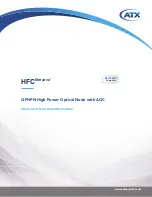
1. Downstream RF output level test port (-20dB)
2. Downstream RF output / Upstream RF input
3. Upstream RF test port (-20dB)
4. Power input +5~+8VDC
5. Upstream fiber output
6. Downstream fiber input
7. Grounding lug and screw
8. Mounting screw slot
9. Control buttons
10. 3-digit Status display
11. Power ON /alarm LED
12. Mode LED RF LEVEL power
13. Mode LED Optical in/out power
14. Mode LED Attenuation settings
15. Mode LED Equalization settings (tilt)
1. Downstream RF output port 1
2. Downstream RF output port 2
3. Downstream fiber input
4. Power input +5~+8VDC
5. Grounding lug and screw
6. Mounting screw slot
7. Control buttons
8. 3-digit Status display
9. Power ON /alarm LED
10. Mode LED RF LEVEL
11. Mode LED Optical in/out power
12. Mode LED Attenuation settings
13. Mode LED Equalization settings (tilt)
Figure #1 – QFHPN 2-way Compact Node
Figure #2 – QFHPN 1-way Receive Only Compact Node
1
2
3
4
5
6
7
8
9
10
11
12
13
14
15


