Attero Tech unD4I-L User Manual Download Page 15


unD4I / unD4I-L 


User Manual 

 Attero Tech LLC 2015 

Page 14 

614-00020-06 


3.2 – Software Installation 

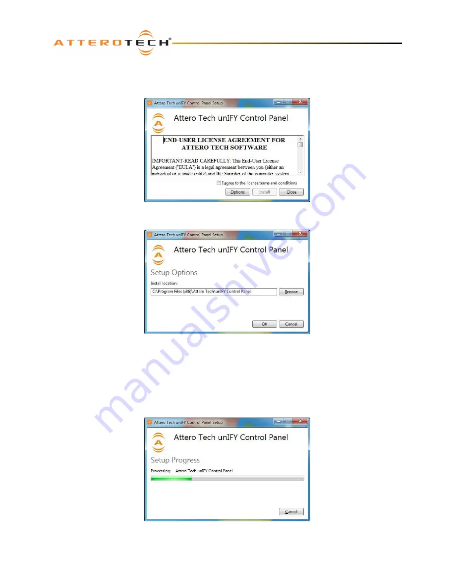
After downloading the application, run the .exe and the first screen to appear will be the license agreement and options 
screen. 


The software will install to a default location of c:\program Files (x86)\Attero Tech\unIFY Control Panel.  Clicking the 
“Options” button allows the user to change the installation location if required though it’s not necessary to change it. 


To select a new installation location, either type in a new path in the edit box, or click on the “Browse” button to browse 
the folder tree for the desired installation location.  Once complete, click the OK button to return to the previous screen. 
 
To continue the install, read the license agreement and check the “I agree…” check box.  Doing so enables the “Install” 
button.  Click the now enabled “Install” button to start the installation of the files. 
 
On Windows Vista or later if the PC has the UAC enabled, a warning pop up will now appear saying the installer is about 
to make changes to your PC.  This needs to be accepted for the installation to complete successfully. 
 
The installer will show a progress screen and will now being transferring files to your PC. 


Once the files are transferred, the installer will show a completion message show whether the installation was successful 
or not. 

Summary of Contents for unD4I-L

Page 1: ...o Tech LLC 1315 Directors Row Suite 107 Ft Wayne IN 46808 Phone 260 496 9668 Fax 260 496 9879 www atterotech com 614 00020 06 unD4I unD4I L Four Input Dante Interface User Manual Date 9 23 2015 Revisi...

Page 2: ...outlet 10 Protect the power cord from being walked on or pinched particularly at plugs convenience receptacles and the point where they exit from the apparatus 11 Only use attachments accessories spe...

Page 3: ...tection against harmful interference when the equipment is operated in a commercial environment This equipment generates uses and can radiate radio frequency energy and if not installed and used in ac...

Page 4: ...Software Installation 14 3 3 Selecting a Network Adapter 16 3 4 Connecting to a Device 16 3 5 Device Identification i 3 6 Device Controls 17 3 7 Dante Debug Mode 17 3 8 Saving and Loading Settings 18...

Page 5: ...l s gain and phantom power status for easy troubleshooting The unD4I and unD4I L can be powered by an external 24VDC power supply ordered separately but also support the use of PoE This allows them to...

Page 6: ...e in decimal The logic inputs can also be used to trigger a customized UDP event message There are several different event modes selectable on an input by input basis When an event is triggered a cust...

Page 7: ...r logic outputs 7 2 x Dante Ethernet interface connector and indicators 8 Power Socket Use with optional 24 V DC supply only 9 Power Link input and output Note All devices have a label on one of the m...

Page 8: ...logic outputs When powering using PoE o Attach the PoE Data Dante I F port to a spare PoE enabled port on a PoE switch using a CAT 5 cable If a midspan injector is being used connect a spare input po...

Page 9: ...r consumption of the unD4I L when sinking all four logic outputs at its maximum sink current is 10W when the rear panel 24V logic supply is used In applications where the unD4I L is used it is recomme...

Page 10: ...unD4I unD4I L User Manual Attero Tech LLC 2015 Page 9 614 00020 06 Figure 4 Network Configuration Example...

Page 11: ...wire unbalanced source to the unD4I connect the positive output of the unbalanced source to the positive input of the unD4I Connect both the source and unD4I input grounds together and short the negat...

Page 12: ...tion for using an analog input may be a volume control where the volume is controlled by a potentiometer The position of the potentiometer can be measured by the unD4I L and a control system can read...

Page 13: ...trol protocol or the unIFY Control Panel software Figure 11 Sink Mode Examples Note If used with an inductive load such as a relay an external freewheeling diode must be placed across the logic output...

Page 14: ...t and output channels won t be visible and routing of audio to and from the device will not be possible In order to configure an unD4I or unD4I L both to set up internal parameters and also setup audi...

Page 15: ...to browse the folder tree for the desired installation location Once complete click the OK button to return to the previous screen To continue the install read the license agreement and check the I a...

Page 16: ...unD4I unD4I L User Manual Attero Tech LLC 2015 Page 15 614 00020 06 If the installation was unsuccessful for any reason the final screen will show an error message...

Page 17: ...te with detected devices The detected devices are listed by their device name Select the device to be configured from the drop down list and then click the Connect button The application will then att...

Page 18: ...line level signal should typically use the 0dB option Choose the gain value that best suits the level of the incoming signal Changing this setting sets both the gain level and whether the 12dB pad is...

Page 19: ...the device can be saved to the selected preset by clicking the Save to Device button Alternately the settings from the selected preset can be loaded and used as the current settings by clicking the R...

Page 20: ...the values and states in real time 4 2 Logic Outputs The Logic Output section shows both the current state of the output as well as allowing control of what the output does For each output there is a...

Page 21: ...e unD4I L determines what step the input is currently on and whether the current step has changed from the last time the input value was read If it determines the step is now different an event messag...

Page 22: ...ing an event message when the digital state of the input changes The valid triggering options are rising falling or both By selecting the triggering mode once the unD4I L detects a logic state change...

Page 23: ...e required Regardless of the type of the message field each must contain an ASCII string of at least one or more characters up to a maximum of 32 characters A termination string for messages is also r...

Page 24: ...s using the 3rd party UDP interface 2 Using Dante Controller look at the devices Product Version by double click on the device in question select the Status tab and look for the Product Version parame...

Page 25: ...via 3 pin depluggable connectors Selectable gains of 0dB 15dB 30dB and 45dB and a 48V phantom power option shall be provided via software for each input The unit shall provide two RJ 45 network conne...

Page 26: ...ICES 003 CE EN55022 RoHS Audio Inputs Input Type Balanced and RF filtered Gain 0dB 15dB 30dB and 45dB software selectable 12dB pad software selectable Input Impedance 1 8K ohms at any gain Maximum In...

Page 27: ...614 00020 06 APPENDIX A Reference Documents The following table lists the relevant reference documents Document Title Location unIFY 3rd Party Software API Registered users area on website Dante Firmw...

Reviews: