background image


Page 5 

                    1315 Directors Row Suite 107 Fort Wayne, IN 46808  

  (260)496-9668  

  www.atterotech.com 

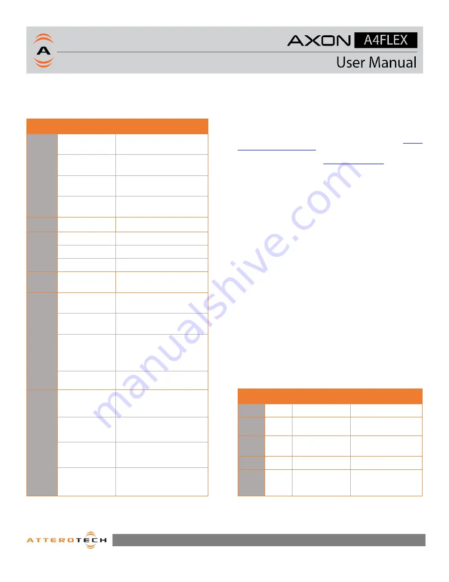
2.4 – LED Status Indications 

The  A4FLEX  is  equipped  with  various  LED  indicators.  The 

following chart indicates the available LED status information: 


LED  

Device Status 

           Status Indication 

(LED) 

Multiple 

Booting 
 

Solid Yellow 

(PWR / NET / USB / I/O LEDs) 

Critical error 
 

Slow Blink Red 

(PWR / NET / USB / I/O LEDs) 

“Identify” mode 
 

Slow Blink Whie 

(PWR / NET / USB / I/O LEDs) 

Firmware Update 

Fast Blink Blue 

(PWR / NET / USB / I/O LEDs) 

PWR 

Power on (OK) 

White 

NET 

No PTP sync 

Solid Red 

PTP sync – Slave 

Solid Green 

PTP sync - Master 

Solid White 

USB 

USB Host 
Connected 

White 

(USB LED) 

I/O 

Ch1-Ch4 Input 

Off 


Ch1-Ch3 Input, 

Ch4 Output 

Green 


Ch1,2 and 4 
Input, 
 Ch 3 Output 
 

Blue 


Ch1-Ch2 Input, 
Ch3-Ch4 Output 

White 

SIG 

Signal below -
60dBFS 


Off


Signal between -
60dBFS and -
20dBFS 

Green 

Signal between -
20dBFS and -
3dBFS 

Yellow 

Signal above -
3dBFS 

Red 

9 - Status Indicators 

3

 – Device Configuration 

The A4FLEX product is supported for setup and monitoring within 

Attero  Tech’s  unIFY  Control  Panel  software.  Additionally,  QSYS 
Designer  plugins  are  available  to  provide  seamless  integration 

with the QSYS DSP platform. 
 

For  a  complete  description  of  the  A4FLEX  software  controlled 
features  found  in  unIFY  Control  Panel,  consult  the 

on-line 

software support resources

 for on the Attero Tech support desk. 


Refer to the support desk an

A4FLEX product page

 on the Attero 

Tech website for the latest links to integration support resources. 


3.1 – IP Address Setup 

*************************  IMPORTANT  ************************** 

Failure  to  correctly  configure  IP  addresses  will  not  allow  an 
A4FLEX device to correctly authenticate in the unIFY Control Panel 

software, and configuration and control to and from the A4FLEX 
will not be possible. 

******************************************************************* 


In order to configure an A4FLEX or to update A4FLEX firmware, a 
PC will need to be able to communicate with it over the network. 

While all A4FLEX devices will be discovered regardless of the IP 
address  setup  on  the  PC  (the  A4FLEX  utilizes  mDNS  for  device 

discovery), full communication can only occur if the PC and the 
device have compatible IP addresses. 

 
By  default,  A4FLEX  is  set  to  get  a  dynamic  IP  address.  If  the 

A4FLEX  device  does  not  find  a  DHCP  server  to  retrieve  an  IP 
address from, it will give itself a  local link address (sometimes 
also known as an automatic private IP address or APIPA) instead. 

A local link address is always in the range 169.254.x.y. 
 

To ensure communication, the PC can either be also set to get a 
dynamic IP address, or be given a static IP address in the range 

169.254.x.y. In some cases the PC 
 

3.2– Networking Information 

The A4FLEX uses the following IP addresses, services and ports 
for communications on the network. 


Port 

TCP / 

UDP 

Mulitcast IP 

Description 

68 

UDP 

N/A 

DHCP  

5353 

UDP 

224.0.0.251 

mDNS – Device 

Disvovery 

319-

320 

UDP 

224.0.1.129 

PTP – Clocking 

(Domain 0) 

49494 

UDP 

N/A 

A4FLEX control 

49495 

UDP 

239.255.255.255 

A4FLEX status and 

metering 

10 - Ports and Protocols 


Summary of Contents for AXON A4FLEX

Page 1: ...614 00050 Rev 01_a Attero Tech LLC 2019 7 1 2019 AES67 Networked Audio Connectivity Interface ...

Page 2: ...safety If the provided plug does not fit into your outlet consult an electrician for replacement of the obsolete outlet 10 Protect the power cord from being walked on or pinched particularly at plugs convenience receptacles and the point where they exit from the apparatus 11 Only use attachments accessories specified by Attero Tech 12 Use only with the cart stand tripod bracket or table specified ...

Page 3: ...breach of warranty as outlined above NEITHER ATTERO TECH LLC NOR ANYONE INVOLVED IN THE PRODUCTION OR DELIVERY OF THE EQUIPMENT SHALL BE LIABLE FOR ANY INDIRECT SPECIAL PUNITIVE CONSEQUENTIAL OR INCIDENTAL DAMAGES ARISING OUT OF THE USE OR INABILITY TO USE THIS EQUIPMENT EVEN IF ATTERO TECH LLC HAS BEEN ADVISED OF THE POSSIBILITY OF SUCH DAMAGES IN NO EVENT SHALL THE LIABILITY OF ATTERO TECH LLC E...

Page 4: ...stallation 2 2 1 Mounting 2 2 2 Power Network Connectivity 3 2 2 1 Daisy Chain Switched Configuration 3 2 2 2 Independent VLAN Configuration 4 2 3 Audio I O Connections 4 2 4 LED Status Indications 5 3 Device Configuration 5 3 1 IP Address Setup 5 3 2 Networking Information 5 3 3 Audio I O and DSP Setup 6 3 4 Logic I O Setup 7 3 5 Factory Reset 7 3 6 Firmware Updates 7 4 ARCHITECTS ENGINEERS SPECI...

Page 5: ...resentation systems in corporate higher education hospitality and courtroom venues 1 1 What s in the Box The A4FLEX comes supplied with the following o Axon A4FLEX device o Euro block mating plugs o 1 6ft Mini USB cable o Two removable mounting flanges 1 2 Optional Accessories o 1 RU Rack Surface Mount Tray Kit 1 3 Device Features Front Panel 1 2 3 Description 1 LED status indicators 2 USB audio c...

Page 6: ...e A4FLEX is a 1 3 rack width device and 1RU high It can be mounted into a rack using the rack tray accessory sold separately The accessory tray can hold up to three 1 3rd rack width AXON units When used with the rack shelf the A4FLEX is attached to the tray with mounting screws installed through its base The L brackets are then used as the rack ears by installing them to the side flanges of the tr...

Page 7: ...nt conditions on the PoE PSE 2 2 1 Daisy Chain Switched Configuration By default the Ethernet ports on an A4FLEX act as a two port switch This be useful if for example there is a second unit in the same physical location as the A4FLEX Its network can be connected to the A4FLEX instead of having to have a separate home run back to the switch thus creating a daisy chain saving time and cabling and n...

Page 8: ...ed for installation though care must be taken not introduce grounding issues into the system by doing so 2 3 Audio I O Connections The A4FLEX features two dedicated audio inputs two flexible I O that can be configured as audio inputs or outputs and two dedicated amplified outputs Source Shield A4FLEX Input 7 Balanced Wiring Example The audio inputs and outputs use a balanced connection If connecti...

Page 9: ...esk and A4FLEX product page on the Attero Tech website for the latest links to integration support resources 3 1 IP Address Setup IMPORTANT Failure to correctly configure IP addresses will not allow an A4FLEX device to correctly authenticate in the unIFY Control Panel software and configuration and control to and from the A4FLEX will not be possible In order to configure an A4FLEX or to update A4F...

Page 10: ...d through unIFY Control Panel Each analog audio input features switchable 48V phantom power mic line pad and supports up to 42 dB of adjustable preamp gain in 1 dB steps Each analog line output has a switchable pad allowing the output to be either at either mic or line level The internal audio DSP features basic audio processing as shown in the diagram below 11 DSP Signal Flow Diagram ...

Page 11: ...y reset is a useful way of quickly restoring communications with a device which has an unknown static IP address as a factory reset returns the device s network settings to getting a dynamic IP Having successfully completed a factory reset of the device setting the PC s IP address to also obtain a dynamic IP address should then allow the PC to communicate fully with that device The factory reset b...

Page 12: ...trolled devices The device shall provide the ability to interface USB digital audio from a connected device to and from an AES67 network The AES67 networked audio interface shall support transmission and reception of 8 independent channels in both directions at 48 kHz 24 bit with 1 ms packet times Internal DSP on the device shall support signal mixing of all I O equalization and output limiting Th...

Page 13: ...sition 16 28 AWG Gain 8 dB to 34 dB gain 1 dB increments Input Impedance 2K ohms at any gain Maximum Input Levels Pad Active 8 dB Gain max input 16 5 dBu 24 dBu w pad 34 dB gain 25 5 dBu 17 5 dBu Phantom Power 48V software selectable per channel THD N 0 05 1 kHz 3 dBFS input 20 20kHz Frequency Response 20 20 kHz 1 dB Line 50 20kHz 1 dB Mic EIN 125 dBu Audio Line Outputs Connector Type 3 81mm Euro ...

Reviews: