background image

13

March 2006

Bill Acceptor - JCM UBA-10-SS

Bill Acceptor Tests

Description

The host machine provides test routines for bill

acceptor diagnostics.
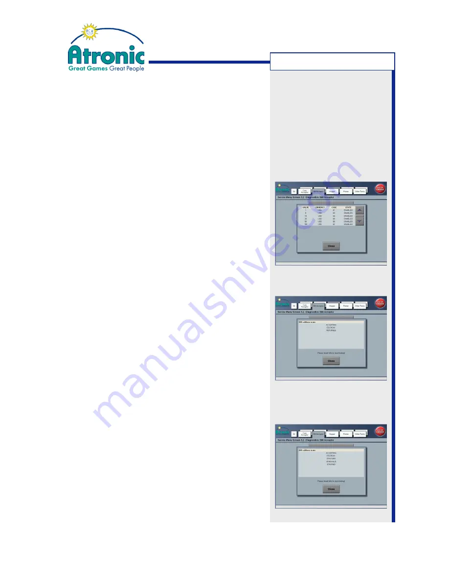
Bills enabled

Use this menu to check which bills are enabled /

disabled by the host machine.

1. Open maindoor and press service button to enter

the Service Menu.

2. Enter "Service Menu / Diagnostics / Bill Acceptor /

Bills Enabled". A list with bill values, currency, code

and state is displayed.

Validator Test With Stacking

Use this menu to test bill acceptance with stacking.

Make sure to have hopper drawer keys and cashbox

keys at hand to retrieve bills after testing.

1. Open maindoor and press service button to enter

the Service Menu.

2. Enter "Service Menu / Diagnostics / Bill Acceptor /

Validator Test With Stacking".

3. Insert bills and check acceptance and stacking.

Validator Test Without Stacking

Use this menu to test bill acceptance without

stacking. After validation the bill is rejected.

1. Open maindoor and press service button to enter

the Service Menu.

2. Enter "Service Menu / Diagnostics / Bill Acceptor /

Validator Test Without Stacking".

3. Insert bills and check acceptance.

T

ROUBLESHOOTING

Note

:

Depending on game software

version the layout of the

menus may vary.

Summary of Contents for JCM UBA-10-SS

Page 1: ...www atronic com Rev 1 0 March 2006 Bill Acceptor JCM UBA 10 SS for use in Atronic e motion and Harmony gaming machines ...

Page 2: ...2 March 2006 Bill Acceptor JCM UBA 10 SS Bill Acceptor JCM UBA 10 SS Rev 1 0 Rel March 2006 2006 Atronic All rights reserved RELEASE INFO ...

Page 3: ...CM UBA 10 SS bill acceptor that is installed in an Atronic e motion or Atronic Harmony gaming machine Components 1 Acceptor Unit 2 Upper Guide Access Lever 3 Front Bezel 4 USB Connector 5 DIP Switch Block 6 Diagnostic LEDs 7 Front Bezel Connector 8 Front Access Door 9 Transport Unit Release Lever 10 Cash Box 11 Frame 12 Centering Guide Release Port 13 Interface Connector INTRODUCTION ...

Page 4: ...irements DC 12V 5 Standby 220mA Operating 1 6A Cash Box Capacity 500 notes or more Processing Speed Approximately 5 sec from bill insertion to completion of stacking Bill Types Accepted Width 62 85mm Length 120 165mm up to 170mm with WBA steel cash box Environment Operating 5 to 50 C Storage 20 to 60 C Humidity 30 85 RH non condensing Avoid direct sunlight contact Indoor use only Weight Approximat...

Page 5: ...e the Transport Unit If the acceptor is mounted to the machine cabinet it is necessary to pull out the transport unit in order to clear a bill jam or for preventive maintenance 1 Press down the transport unit release lever and pull out the transport unit 2 When re installing make sure that the transport unit is properly seated all the way into the frame and the latches are fully engaged 3 Clear bi...

Page 6: ...ull out the transport unit 2 Open the transport unit by pulling on the upper guide access lever 3 Remove the jammed bill 4 Close and re install the transfer unit 5 Clear bill acceptor error message on screen with the audit key Procedure for Cashbox Entrance 1 Take out the cashbox 2 Remove the jammed bill 3 Re install the cashbox OPERATING ...

Page 7: ...eplace scratched or clouded lenses Inspect if lenses are set flush with the bill path If not open and press lenses back into position Procedure to Clean If possible use compressed air for blowing debris from the bill path and the cashbox Use a lint free cloth and a mild liquid detergent mixed with water such as dish detergent or just water Ensure that the cloth is not liquid saturated Wipe the bil...

Page 8: ... to download only files approved by Atronic 6 Click the DOWNLOAD button to start the soft ware download Do not interrupt the download pro gress 7 When the download has completed click on the OK button and close the downloader application 8 Power down the host machine and unplug the USB cable 9 Power up the host machine for re initialization or host machine SOFTWARE DOWNLOAD Note If the host machin...

Page 9: ...e CPU board Change the CPU board Change the CPU board Change the CPU board Check stacker encoder board and change as required Check stacker motor and change as required Check stacker encoder board and change as required Check exit sensor board and change as required Check exit sensor board and change as required Check stacker encoder sensor for dirt and scratches Change the lower sensor board Tran...

Page 10: ...nses for dirt or scratches Check upper sensor board Remove paper and clean the lenses Check upper and lower sensor board Remove paper and clean the lenses Check upper and lower sensor board Check lenses for dirt or scratches Check upper sensor board Remove paper and clean the lenses Check upper and lower sensor board Remove paper and clean the lenses Check upper and lower sensor board Remove paper...

Page 11: ...ains on the rollers belts and lenses The unit has been disassembled but no calibration has been carried out Wrong or old software Sensor lenses are loose or missing Corrective Action Required Verify that the harness is properly connected Check fuses at host machine F2 on filterboard power Note The small red LED next to the DIP switch block indicated power available when lit Re download the correct...

Page 12: ...ntering guide release ports 12 Download the correct software Make sure the programmed software supports all bills being used Check software specifications for supported bill denomination bill issuing year etc Enable all denominations by setting all DIP switches to OFF Checkforerrormessagesdisplayedonscreen Turnauditkey Check Service Menu Diagnostics Bill Acceptor Bills Enabled for disabled bills C...

Page 13: ...th stacking Make sure to have hopper drawer keys and cashbox keys at hand to retrieve bills after testing 1 Open maindoor and press service button to enter the Service Menu 2 Enter Service Menu Diagnostics Bill Acceptor Validator Test With Stacking 3 Insert bills and check acceptance and stacking Validator Test Without Stacking Use this menu to test bill acceptance without stacking After validatio...

Page 14: ...Photo coupler 0 Volt DC Interface Power 8 Not in use Do not connect 9 Not in use Do not connect 10 Not in use Do not connect 11 Not in use Do not connect 12 Not in use Do not connect 13 GND RS232C 0 Volt DC Interface Power 14 LED Power Test Status LED anode 15 Not in use Do not connect 16 Not in use Do not connect 17 Not in use Do not connect 18 LED Out TTL4 Test Status LED cathode 19 Not in use D...

Reviews: