Atomos ZATO CONNECT User Manual Download Page 19

and its details. The three word code is displayed on the image of the device and the device
type appears. When your device is connected to Atomos Cloud, a green circle will appear
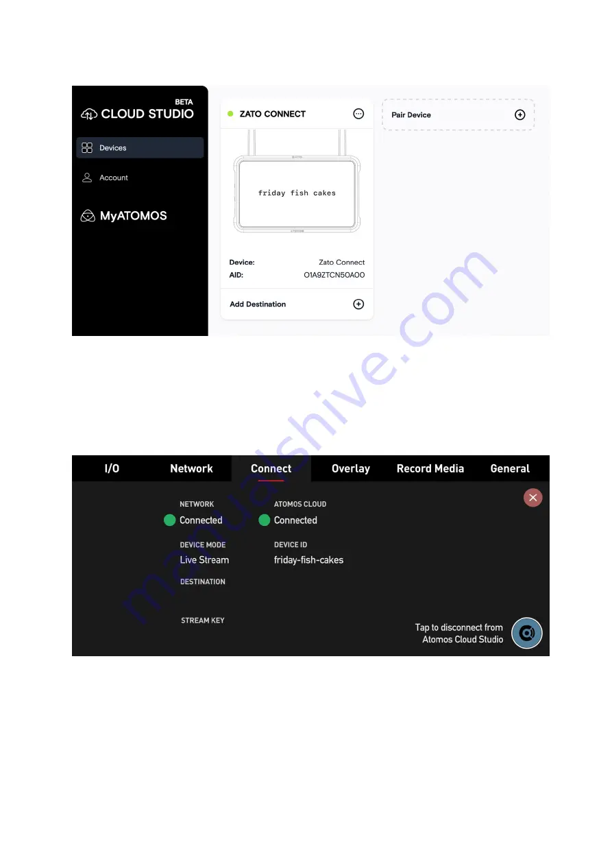
next to the device nickname at the top of the device box.

The Connect Menu page of your ZATO CONNECT will also update, with another green circle
indicating that you're connected to the Atomos Cloud. The current mode will also be
displayed under Device Mode, with Device Id used for pairing right next to it.

Note:

 Since the destination and stream key have not been configured yet, these fields will

stay empty for now.

Next, you will need to configure the services for this device at 

atomos.cloud

. Tap on the +

symbol next to Add Destination in the device box and a new window will open, displaying
the destination options.

Summary of Contents for ZATO CONNECT

Page 1: ...52JATOMOS ZATO CONNECT USER MANUAL Al OMOS...

Page 2: ...FEATURES The front of the ZATO CONNECT is almost entirely covered by its 5 SuperAtom IPS display On the right side of the device you ll find the multi purpose Power button as well as the ZATO CONNECT...

Page 3: ...side of the enclosure houses the 3 5mm Mic Line Input jack a 3 5mm Headphone jack and a 2 5mm Serial LANC connector The primary I O of the ZATO CONNECT is located at the rear of the device It consist...

Page 4: ...USB C to Ethernet adapter Two SMA connectors are placed along the top and are where you want to connect the included WiFi antennas to In the center there s the NP F L Series battery slot An additional...

Page 5: ...he device s ventilation holes along the top and bottom edges of the enclosure which should not get obstructed or covered up during use To provide mounting flexibility the ZATO CONNECT includes 1 4 20...

Page 6: ...adapter Once these requirements are met you can turn on the ZATO CONNECT by shortly pressing the power button on the right side of the device To power o the device again hold the power button for 4 s...

Page 7: ...power output specifications may result in the ZATO not turning on or behaving unpredictably Note If the ZATO s operating voltage drops to 6 5V it will display a warning message via a pop up dialog as...

Page 8: ...p Menu Bar You will also notice the Top Menu Bar which summarizes the most significant parameters when it comes to using the ZATO CONNECT IN Highlights the input signal specification resolution and fr...

Page 9: ...ut if no SD Card is inserted Note It is also used to get back into Record Live View mode if you ve previously switched over to Playback mode Play Button Press to switch into Playback mode Once in Play...

Page 10: ...s up the 1 91 Frame Guide 4 3 Brings up the 4 3 Frame Guide 1 1 Brings up the 1 1 Square Frame Guide 4 5 Brings up the 4 5 Frame Guide 9 16 Brings up the 9 16 Frame Guide Menu Icon Provides quick acce...

Page 11: ...To the right under SIGNAL the ZATO outlines the specifications of the input signal The signal specification consists of a short version of the resolution the scan type and the frame rate Example 1080p...

Page 12: ...utput a signal at half of the original frame rate Example HDMI Input 1080p60 HDMI Output 1080p60 USB UVC Output 1080p30 Audio The ZATO CONNECT comes equipped with a built in Audio Mixer The mixer cons...

Page 13: ...final adjustments via the Output Mix slider Note Both Line 10 dBu and Mic Levels 40 dBu are supported You may switch between them by pressing the label text on the right side of the menu window...

Page 14: ...d Ethernet WiFi To connect your ZATO CONNECT to a WiFi network either at home your studio your phone hotspot or any other WiFi access point enable the WiFi switch on the left of this menu Within secon...

Page 15: ...ction is established successfully a green checkmark is displayed to confirm the connection status If the password you entered is incorrect or if the connection can t be established the ZATO displays a...

Page 16: ...the switch on the left to disable it Ethernet Before establishing a network connection via Ethernet ensure that WiFi is disabled Next connect the included USB C to Ethernet dongle to the port labeled...

Page 17: ...t cable to the USB C to Ethernet adapter If you ve selected Using DHCP in the previous step the ZATO will automatically fetch its network configuration parameters from the Switch Router you re connect...

Page 18: ...ion to the Atomos Cloud Note Before connecting to the Atomos Cloud your device must first be connected to the Internet You can connect your ZATO CONNECT to the Internet via WiFi or via the included US...

Page 19: ...with another green circle indicating that you re connected to the Atomos Cloud The current mode will also be displayed under Device Mode with Device Id used for pairing right next to it Note Since th...

Page 20: ...vice or navigate to atomos cloud on a desktop browser Either sign up for a new account or log in to an existing account Once logged in press the Pair Device button and enter the three words from the Z...

Page 21: ...be prompted to enter your credentials and other settings for that destination Once you ve configured your destination engage the ON OFF switch to send the streaming destination information including t...

Page 22: ...ream Key fields which were previously empty For privacy purposes the Stream Key is hidden but you can toggle its visibility by tapping on the Eye icon on the left Once all the destination information...

Page 23: ...will begin To end the live stream just press the ZATO s Live button again The stream will automatically end when it s no longer receiving an RTMP S feed o Studio LIVE0 31 Title ZATOCONNECTTestStreamv...

Page 24: ...is 1920 x 1080 Pixels Alpha transparency is fully supported After you transferred your overlay graphics to the SD card insert it into the SD card slot on the right side of the ZATO CONNECT Add Media I...

Page 25: ...se the confirmation message by pressing Ok The process is identical for the remaining media slots so you ll have to repeat this procedure seven more times if you want to fill them all up Note To reset...

Page 26: ...set Press on the Preset you want to use and then on Edit allowing you to configure it freely and to your liking Next select the Overlay Position you want to assign a PNG graphic to After that select t...

Page 27: ...y button in the bottom right corner of this menu Once the Apply button is pressed it changes its state to Hide so if you press it again it will hide all overlays currently applied to the image To conf...

Page 28: ...rd playback Choose SD Card playback or HDMI inputs as PiP sources over USB Choose SD Card playback or USB inputs as PiP sources over HDMI PiP sources can be set to 1 out of 4 positions top left top ri...

Page 29: ...put source that the PiP overlay will sit on top of For this connect either an HDMI device to the ZATO s HDMI Input or a USB UVC device to its USB 1 port Note USB 2 is a multi purpose port that can onl...

Page 30: ...ect a clip for playback After selecting your clip it will be displayed full screen with playback controls appearing on top of the bottom menu row IN1080p24 ouT1080p24 AUDIOMIX RECH 264ST 01 05 13 LIVE...

Page 31: ...u may now physically connect your additional PiP input source to the ZATO CONNECT HDMI or USB UVC or select the SD Card if your PiP overlay should be playing back a pre recorded file Depending on your...

Page 32: ...o presets for small and large PiP sizes on the right side of the PiP menu Configuring Picture in Picture via the Quick Access Bottom Row Menu If you want to configure your PiP setup without entering t...

Page 33: ...options when the ZATO is in its recording mode and not streaming to a platform like YouTube or Twitch For regular recording there are 4 compression variants LQ 5 Mb s MQ 12 Mb s HQ 50 Mb s XQ 80 Mb s...

Page 34: ...the Date Time tab that can be found in the General menu Media Info In this menu you find out how much time remains for recording in the previously selected H 264 compression variant Below that there...

Page 35: ...n making it impossible to accidentally change any device settings On the right side there s a battery status indicator for NP F L Series batteries that may be attached to the battery slot on the rear...

Page 36: ...ead Not Connected instead Display The Display menu only contains one large horizontal slider allowing you to adjust the brightness backlight strength of the ZATO CONNECT Date Time In this menu you can...

Page 37: ...on the ZATO CONNECT the AID and the firmware Build Info You ll also find the Reset Device button here which resets the ZATO to its factory state Pressing it and confirming the warning dialog removes e...

Page 38: ...Pressing the Download License button creates a TXT file on the SD card including licenses for the 3rd party software libraries we use on the ZATO CONNECT...

Page 39: ...wer lock Screen Network Con fi g Settings Auto Join WiFi DHCP Manual Network Con fi guration Power Input voltage 6 2V to 16 8V Operating power 10W Compatible batteries 1 x NP F L Series Battery voltag...

Page 40: ...e Naming Standard Unit Name Date Time Video Output HDMI 1 x HDMI 1 4 Network Ethernet via included USB C Dongle Wi f WiFi 5 USB Host USB Webcam Atomos Cloud Connect to Atomos Cloud Studio services Cel...

Page 41: ...o 1080p60 Monitoring SDR Rec 709 Multi Input Switching Picture in Picture PIP Picture in Picture from webcams USB UVC devices HDMI inputs and recorded clips on SD Card Select position and size of PiP...

Page 42: ...colored caps White Red Yellow Black Green 2 x Antenna Top Caps 2 x Antenna Mount Cover 1 x USB C to USB C Cable USB C to Ethernet Adapter 1 x Antenna Storage Pouch 1 x Quick Start Guide 1 x Screen Clo...

Page 43: ......

Reviews: