Page 15/28 (26/21)
Assembly and adjustment
Preparation
• Dismantle gas spring inclusive bowden
cable.
• Make sure that the components listed
in the scope of delivery are completely
available and undamaged.
• Before assembly of the motor unit, ensure
the grey reducing bushes 010/15 are
plugged into the fork head on the lifting
rod side of the motor.
Assembly
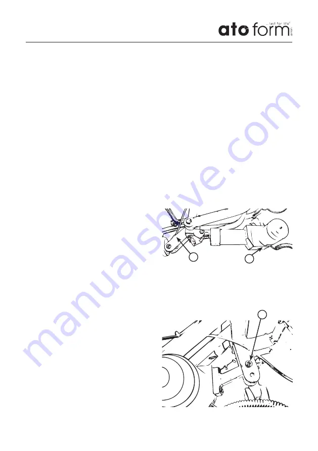
• Start with the assembly of the motor on
the side of the lifting rod (pic.1, no.1).
The side of the housing with the type
plate (2) on it must point downwards
when the motor is installed (note the
“UP” sticker!) During assembly, ensure
the correct positioning of the fork head
(pic.2, no.3) with little play in the motor
mounting. Use the enclosed plastic discs
for assembly. When screwing the fork
head it must not be jammed and must
remain moveable!.
• Then assemble the motor side mounting
with the enclosed screws to the base of
the frame. The mounting when installed
must point diagonally upwards from the
motor housing.
pic. 1
front side
rear side
pic. 2
1
2
3


