7
English
English
8
Note:
Both receivers’ output will be mixed together as per the
individual receivers’ volume settings controlled
by volume
knobs
. If separate signals are required for each instrument
then the XLR outputs must be used, however, note they are
not line level or adjustable. The SUM out is best utilized for
switching between separate transmitters during performance
with only one audio signal
at a time fed to the instrument amplifier. For balanced output,
plug an audio cable with an XLR connector into the XLR
Balanced Mic Out socket for each receiver and plug the other
end into your mixing board or amplifier inputs accordingly As
when making any connection, make sure the amplifier or
mixing board volume is at the
minimum level before plugging in the receiver to avoid
possible sound system damage.
Your receiver is now operational and ready to use. Once you
have completed the above steps, proceed to the following
instructions for the handheld or instrument transmitter.
Note:
Only one transmitter can be used with one receiver. It
is not possible to use two transmitters on the same frequency
and mix the output of these transmitters into one wireless
receiver. However, as this is a two receiver unit, two transmit-
ters on separate frequencies can be utilized, one with each
receiver.
Setting up the Transmitter
The BT bodypack requires two AA size batteries to operate.
To install the batteries into the battery compartment, lift the
Battery Compartment Door by grabbing the two
spring-loaded locking tabs and pull out, exposing the Battery
Compartment. Insert two fresh AA batteries according to the
correct polarity as indicated on the transmitter body. Close
the battery cover, ensuring the cover is snapped shut. Fresh
alkaline batteries can last provide up to 8-10 hours of
operation, but in order to ensure optimum performance it is
recommended that the batteries be replaced after 6-8 hours
of use or as indicated necessary by the flashing
Battery
Meter “BATT” Icon
.
Connecting Input Audio Source
Use the Audio Input 3 pin
三
locking mini jack for connecting
the audio input cord from lapel mic (LT), Headmic (LT/HM), or
instrument (GT), depending on which version transmitter is
being used. Secure the connection to the cable by lining up
the slot of the mini connector and turning the ring to securely
lock in.
Powering the Transmitter On/Off
To turn on the transmitter, slide the
Power Off/On Switch
.
The LCD backlight will light up. The unit is now on. After ten
seconds the backlight will automatically turn off. The
Channel
) and
Battery Meter
remain on in normal operation.
As many of the LCD battery levels should stay lit as possible,
indicating usable battery strength. As the batteries weaken,
fewer of the level indicators stay lit until only one bar shows,
which will then flash to warn that the batteries are now too
low andshould be replaced as soon as possible. To preserve
battery life, turn the transmitter off when not in use. To turn
the transmitter off, slide the Off/On switch and then “OFF”.
The LCD will display “OFF”, no LCD or backlight is lit up and
the unit will be off. At Power Off the transmitter will store the
last settings entered and re-display
them at the next power on where it can be reprogrammed to
any new Channel or Volume level at the first time of use or
anytime later. The factory default setting for Volume 0dB is
same for all transmitters. These settings are optimal for most
applications.
Setting up the Transmitter
The requires two AA size batteries to operate. To install the
batteries onto the battery compartment, unscrew the
Battery
Compartment Cover
by turning counterclockwise until
loose and slide down
the cover, exposing the
Battery Compartment
. Insert two
fresh AA batteries according to the correct polarity as
indicated on the transmitter body. Screw the battery cover
back onto the microphone, making sure it is securely
tightened. Fresh alkaline batteries can provide up to 8-10
hours of operation, but in order to ensure optimal
performance it is recommended that the batteries be
replaced after 6-8 hours of use or as indicated to be
necessary by the flashing
Battery “BATT” Meter Icon
.
Powering the Transmitter On/Off
To turn on the transmitter, slide the
Power On/Off Switch
to
the “ON” position. The LCD backlight will light up, indicating
the unit is now on. After ten seconds the backlight will
automatically turn off to conserve battery life. The
Channel
and Battery Meter
indicator icons stay on for normal
operation.
As many of the LCD battery levels should stay lit as possible,
as they indicate usable battery strength. As the batteries
weaken, fewer of the level indicators will stay lit until only one
bar shows, which will then flash to warn that the batteries are
now too low and should be replaced as soon as possible with
fresh ones.
To preserve battery life, turn the transmitter off when not in
use. To turn the transmitter off, slide the power on/off switch
to the “OFF” position. The LCD will display “OFF,” no LCD or
backlight is lit up and the unit will be off.
At Power Off the transmitter will store the last settings
entered and re-display them at the next power on where it
can be reprogrammed to any new frequency at the first time
of use or anytime later.
Programming the Transmitter to the Selected channel
The transmitter can be programmed to the same channel as
selected for the receiver, either via automatic synchronization
using the IR Sync function or manually on the transmitter
itself.
IR Sync Programming:
Use the wireless
IR LED Receptor Sensor
to download
pre-programmed channel from the receiver. Start programming
by holding the IR LED Receptor about 6-12” from the
receiver’s
IR LED Window
, then press the
IR Sync Button
on the receiver to be used, the IR LED will light up red and
stay for about five seconds. This indicates IR transmission is
in progress and IR data is transferring during this period.
Upon successful data transfer (usually in about three
seconds) the IR LED stops and the transmitter’s backlight will
light up and the transmitter will transmit a radio signal on the
same frequency as the receiver. The Signal Strength on the
receiver’s LCD display will then light up, indicating that the IR
link is completed.
Note:
If procedure is not done correctly during the five
seconds of active data transfer, the receiver and the transmit-
ter do not link and transmitter’s previous programmed
channel remains unchanged.
The IR link is infrared light and thus works best when this
data transfer is accomplished in a light-shielded or darker
environment. It may not be successful in a brightly lit area. If
the transfer fails, repeat the procedure in a darker location or
somehow shield the link from outside light to successfully
program the transmitter with the pre-programmed group and
channel info from the receiver.
Operating the Handheld Transmitter
During normal operation with the unit powered ON, the
transmitter power level can be changed by sliding the On/Off
switch to the “ON” position and the microphone is now ready
to use. The receiver’s
RF Signal Meter
should now be on,
indicating a received signal from the transmitter. Adjust the
volume of the receiver per Connecting the Audio Output
section above.
Note:
Avoid acoustic feedback (howling or screeching) by
taking care in selecting PA volume, transmitter location and
speaker placement.
The RF Signal meter on the receiver’s LCD display should be
“ON” in normal operation.
Programming the Transmitter to the Selected Channel
The transmitter can be programmed to the same channel as
selected for the receiver, either via automatic synchronization
using the IR Sync function or manually on the transmitter
itself.
IR Sync Programming:
Use the wireless
IR LED Receptor Sensor
to download
pre-programmed frequency from the receiver. Start program-
ming by holding the IR LED Receptor about 6-12” from the
receiver’s
IR LED Window
, then press the
IR Sync Button
on the receiver to be used, the IR LED will light up red and
stay for about five seconds. This indicates IR transmission is
in progress and IR data is transferring during this period.
Upon successful data transfer (usually in about three
seconds) the IR LED stops and the transmitter’s backlight will
light up and the transmitter will transmit a radio signal on the
same frequency as the receiver. The Signal Strength on the
receiver’s LCD display will then light up, indicating that the IR
link is completed.
Note:
If procedure is not done correctly during the five
seconds of active data transfer, the receiver and the transmit-
ter do not link and transmitter’s previous programmed
channel remains unchanged.
The IR link is infrared light and thus works best when this
data transfer is accomplished in a light-shielded or darker
environment. It may not be successful in a brightly lit area. If
the transfer fails, repeat the procedure in a darker location or
somehow shield the link from outside light to successfully
program the transmitter with the pre-programmed group and
channel info from the receiver.
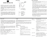
Handheld Microphone Transmitter
Bodypack Transmitter