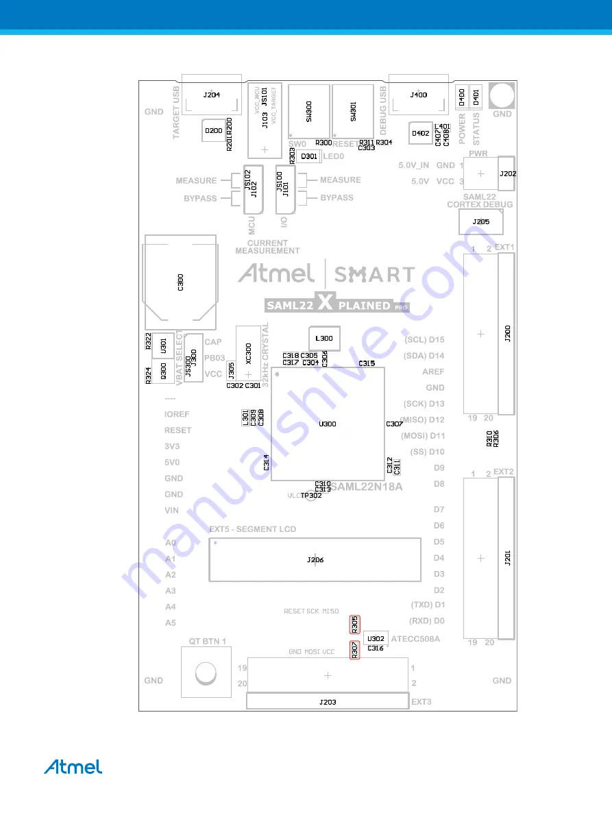
Figure 4-4. Assembly Drawing Top
Atmel SAM L22 Xplained Pro [USER GUIDE]
Atmel-42474B-SAM-L22-Xplained-Pro_User Guide-12/2015
31
Page 1: ...s easy access to the features of the Atmel ATSAML22N18A and explains how to integrate the device in a custom design The Xplained Pro MCU series evaluation kits include an on board Embedded Debugger an...
Page 2: ...ment LCD Connector 13 3 5 3 Xplained Pro Power Header 14 4 Hardware User Guide 15 4 1 Power Distribution 15 4 2 Connectors 15 4 2 1 Xplained Pro Standard Extension Headers 16 4 2 2 Segment LCD Connect...
Page 3: ...38 6 Hardware Revision History and Known Issues 40 6 1 Identifying Product ID and Revision 40 6 2 Revision 4 40 6 3 Revision 2 40 6 3 1 Pin out Changes 41 6 3 2 CryptoAuthentication Device 41 6 3 3 As...
Page 4: ...cope information Programming and debugging including power measurements Data Gateway Interface SPI I2C four GPIOs Virtual COM port CDC Embedded current measurement circuitry with Atmel Data Visualizer...
Page 5: ...Figure 1 1 SAM L22 Xplained Pro Evaluation Kit Overview Atmel SAM L22 Xplained Pro USER GUIDE Atmel 42474B SAM L22 Xplained Pro_User Guide 12 2015 5...
Page 6: ...for evaluation and demonstration of features and capabilities of different MCU families Atmel Studio Free Atmel IDE for development of C C and assembler code for Atmel microcontrollers Atmel sample st...
Page 7: ...gment LCD connector is required to use the kit Design Documentation Package containing CAD source schematics BOM assembly drawings 3D plots layer plots etc Hardware Users Guide in PDF format PDF versi...
Page 8: ...pplication through terminal software It offers variable baud rate parity and stop bit settings Note that the settings on the ATSAML22N18A must match the settings given in the terminal software Info If...
Page 9: ...switch Pre amplifier Two active filters with gain Control MCU Analog to digital converter Signal processing Control communication interface to the EDBG The current measurement frontend is a high side...
Page 10: ...gain stage 10 A 1 LSB 1 Range 4 High current shunt and low gain stage 100 A 1 LSB 1 Above 100mA the error will increase to 1 LSB 5 at 400mA Maximum current is 400mA The ranges are switched automatica...
Page 11: ...current for connected USB devices and the board itself Recommended maximum is 2A due to the input protection maximum current specification PWR Embedded debugger USB 4 4V to 5 25V according to USB spe...
Page 12: ...part of differential ADC 5 GPIO1 General purpose I O 6 GPIO2 General purpose I O 7 PWM Pulse width modulation alternatively positive part of differential PWM 8 PWM Pulse width modulation alternatively...
Page 13: ...ction Description Common terminal 3 COM3 1 2 COM2 Common terminal 2 Common terminal 1 COM1 3 4 COM0 Common terminal 0 Segment 0 SEG0 5 6 SEG1 Segment 1 Segment 2 SEG2 7 8 SEG3 Segment 3 Segment 4 SEG4...
Page 14: ...to the SAM L22 Xplained Pro kit The kit will automatically detect and switch to any external power if supplied The power header can also be used as supply for external peripherals or extension boards...
Page 15: ...8 Regulator3 3V Power source Power switch Power converter Power consumer VCC_P3V3 Peripherals Power Measurement Select Auto mux disable External5V input EDBG USB Target USB Auto mux with current limit...
Page 16: ...nd EXT3 offer access to the I O of the microcontroller in order to expand the board e g by connecting extensions to the board These headers are based on the standard extension header specified in the...
Page 17: ...EXT3 Shield Crypto and EDBG I C 13 USART_RX PA23 SERCOM2 PAD 1 UART RX 14 USART_TX PA22 SERCOM2 PAD 0 UART TX 15 SPI_SS_A PB21 SERCOM3 PAD 1 SPI SS 16 SPI_MOSI PB00 SERCOM3 PAD 2 SPI MOSI 17 SPI_MISO...
Page 18: ...0 UART TX 15 SPI_SS_A PA17 SERCOM1 PAD 1 SPI SS 16 SPI_MOSI PA18 SERCOM1 PAD 2 SPI MOSI 17 SPI_MISO PA16 SERCOM1 PAD 0 SPI MISO 18 SPI_SCK PA19 SERCOM1 PAD 3 SPI SCK 19 GND Ground 20 VCC Power for ex...
Page 19: ...one segment LCD extension connector for Xplained Pro extensions and supports up to eight COM twenty seven SEG and six touch signals The connector has a standardized pin out as shown in the table below...
Page 20: ...PC21 SLCD LP 41 27 SEG22 PB16 SLCD LP 42 EXT3 28 SEG23 PB17 SLCD LP 43 EXT3 29 SEG24 PB18 SLCD LP 44 EXT3 30 SEG25 PB19 SLCD LP 45 EXT3 31 SEG26 PB20 SLCD LP 46 Shield 32 SEG27 33 SEG28 34 SEG29 35 SE...
Page 21: ...All references to Arduino pin names are taken from the official Arduino schematics of the Arduino Uno Info Note that all pins do not have the exact same functionality as on the Arduino Uno on the shi...
Page 22: ...RX SLCD 2 PB12 D1 TX0 SERCOM3 PAD 0 UART TX SLCD 3 PB11 D2 GPIO SLCD 4 PB14 D3 GPIO SLCD 5 PB15 D4 GPIO SLCD 6 PC14 D5 GPIO SLCD 7 PC15 D6 GPIO SLCD 8 PB20 D7 GPIO SLCD Table 4 8 J901 Digital High J9...
Page 23: ...AM L22 Xplained Pro has a Micro USB connector for use with the SAM L22 USB module labeled as TARGET USB on the kit To be able to detect when a target USB cable is connected in self powered mode a GPIO...
Page 24: ...to the device 4 3 Peripherals 4 3 1 Crystal The SAM L22 Xplained Pro kit contains a 32 768kHz crystal that can be used as clock source for the SAM L22 device The crystal has a cut strap next to it th...
Page 25: ...super capacitor for use with the SAM L22 backup system The super capacitor can be connected to the device by placing a jumper over pin 1 2 on the 3 pin VBAT SELECT header By default the jumper is plac...
Page 26: ...C 8 VCC VCC_TARGET_P3V3 9 PAD GND 4 3 7 Tamper Detection The ATSAML22N18A supports up to five selectable external inputs and one output that can be used for tamper detection When tamper is detected a...
Page 27: ...ging capabilities of the EDBG see Embedded Debugger on page 8 Table 4 19 SWD Connections SAM L22 pin Function Shared functionality PA30 SWD clock Cortex Debug PA31 SWD data Cortex Debug 4 4 2 Virtual...
Page 28: ...ts in the SAM L22 application code For further information on how to configure and use the GPIO monitoring features see Atmel Data Visualizer and the EDBG User Guide Table 4 23 GPIO Lines Connected to...
Page 29: ...measures only the MCU current while the peripherals are supplied directly by the regulator For this configurations place the jumper for I O peripherals into the BYPASS position and the MCU into the M...
Page 30: ...R601 0R XAM ADC_SYNC1 PB04 GPIO XAM ADC sync interfaces to the ATSAML22N18A R600 0R XAM ADC_SYNC2 PB05 GPIO R406 0R EDBG CDC RX PC24 UART TX EDBG CDC and DGI interfaces to the ATSAML22N18A R407 0R EDB...
Page 31: ...Figure 4 4 Assembly Drawing Top Atmel SAM L22 Xplained Pro USER GUIDE Atmel 42474B SAM L22 Xplained Pro_User Guide 12 2015 31...
Page 32: ...Figure 4 5 Assembly Drawing Bottom Atmel SAM L22 Xplained Pro USER GUIDE Atmel 42474B SAM L22 Xplained Pro_User Guide 12 2015 32...
Page 33: ...of the PCB for operation at other voltages To locate the other components see the assembly drawing in the section above When the components are removed the kit can be supplied with a desired voltage t...
Page 34: ...o Current Measurement Headers Related Links Xplained Pro Power Header on page 14 Cortex Debug Connector on page 23 Connectors on page 15 Atmel SAM L22 Xplained Pro USER GUIDE Atmel 42474B SAM L22 Xpla...
Page 35: ...nfigure Open the OPTIONS dialog for the project 2 In the category General Options select the Target tab Select the device for the project or if not listed the core of the device 3 In the category Debu...
Page 36: ...Figure 5 2 Select Debugger Figure 5 3 Configure Flash Loader Atmel SAM L22 Xplained Pro USER GUIDE Atmel 42474B SAM L22 Xplained Pro_User Guide 12 2015 36...
Page 37: ...Figure 5 4 Configure Reset Figure 5 5 Configure Interface Atmel SAM L22 Xplained Pro USER GUIDE Atmel 42474B SAM L22 Xplained Pro_User Guide 12 2015 37...
Page 38: ...ther an Atmel ICE adapter SAM ICE adapter or a 10 pin 50 mil header to squid cable When using a squid cable see the table and figures below for how to connect the SAM ICE to the Xplained Pro board Tab...
Page 39: ...rom another input like the external power header or from the target USB Physically removing the connection between the EDBG and the debug header by removing 0 resistors where available or cutting the...
Page 40: ...number string has the following format nnnnrrssssssssss n product identifier r revision s serial number The product identifier for SAM L22 Xplained Pro is A09 2547 6 2 Revision 4 Touch SLCD1 Xplained...
Page 41: ...N1 PC00_QTBTN1_SLCDX1 PTC Y 4 PB06_QTBTN1_SLCDX1 PTC XY 12 6 3 2 CryptoAuthentication Device SAM L22 Xplained Pro revision 2 has the ATAES132A CryptoAuthentication device mounted The table below shows...
Page 42: ...Figure 6 1 Revision 2 Assembly Drawing Top Atmel SAM L22 Xplained Pro USER GUIDE Atmel 42474B SAM L22 Xplained Pro_User Guide 12 2015 42...
Page 43: ...Figure 6 2 Revision 2 Assembly Drawing Bottom Atmel SAM L22 Xplained Pro USER GUIDE Atmel 42474B SAM L22 Xplained Pro_User Guide 12 2015 43...
Page 44: ...ment 42474B 12 2015 Bug fix on hardware See Hardware Revision History and Known Issues on page 40 for changes 42474A 08 2015 Initial document release Atmel SAM L22 Xplained Pro USER GUIDE Atmel 42474B...
Page 45: ...f the goods Further the user indemnifies Atmel from all claims arising from the handling or use of the goods Due to the open construction of the product it is the user s responsibility to take any and...
Page 46: ...SINESS INTERRUPTION OR LOSS OF INFORMATION ARISING OUT OF THE USE OR INABILITY TO USE THIS DOCUMENT EVEN IF ATMEL HAS BEEN ADVISED OF THE POSSIBILITY OF SUCH DAMAGES Atmel makes no representations or...
Page 47: ...Mouser Electronics Authorized Distributor Click to View Pricing Inventory Delivery Lifecycle Information Microchip ATSAML22 XPRO ATSAML22 XPRO B...