background image


Atmel AVR2060: BitCloud ZigBee Light Link Quick Start Guide [APPLICATION NOTE] 

42004B

AVR

08/2012 

8

RCB board’s LEDs are turned on when light is on and turned off when light is off. When the color light’s color level 
changes LEDs brightness also changes. When a color light receives an identify command from a controller LEDs start 
blinking. 

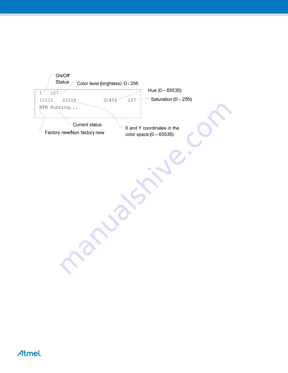
Figure 3-1

 below describes functions of a color light’s LCD screen: 

Figure 3-1.  Color light’s screen on a Key Remote Control board. 


Once a factory new color light is powered on, it starts standard ZigBee scanning and displays 

Scanning 1st...


(indicating that the device is doing ZigBee scan over primary ZLL channels), then 

Scanning 2nd...

 (indicating 

ZigBee scan over secondary ZLL channels) as the current status. When 

Listening...

 is output to the screen the 

color light is ready for touch link. 

3.2.1  Touch link with a controller device 

For touch link a color scene controller is brought closely (10-20cm range) to a color light and the PWR button is pressed 
on the color scene controller for more than three seconds. The color scene remote sends an identify command to the 
color light, which blinks several times with its LEDs or the LCD screen. The touch link procedure may be aborted at this 
moment, if the PWR button is released. To complete the procedure the user should wait for three seconds. 

If touch link is a success, the color light’s screen shows 

NFN Running

... status (where NFN stands for Non Factory 

New). 

After that the color light can be controlled by commands sent from the color scene controller. 

3.2.2  Reset to the factory new state 

There are two ways to reset a color light device to the factory new state: sending a command from a color scene 
controller and using the PWR button if the color light is assembled with a Key Remote Control board. 

To trigger reset of a color light to factory new: 


 Select the target color light using the SEL button on the color scene controller 


 Hold R1, R2 and PWR buttons, altogether, on the color scene controller for three seconds 

A color light assembled with a Key Remote Control board may be reset to the factory new state in the following way: 


 Switch off the device by shifting back the red button at the right side of the RCB board 


 While holding the PWR button on the color light device, switch it on by shifting the RCB’s red button. Wait for 

three seconds and then release the PWR button 

Summary of Contents for AVR2060

Page 1: ...of the BitCloud ZigBee Light Link software development kit SDK a software package for developing ZigBee Light Link profile applications Chapter 1 gives an overview of the software package and support...

Page 2: ...6 2 3 1 1 Precompiled images 6 2 3 1 2 Application workspace 6 2 3 2 Programming with Atmel AVR Studio 6 3 Demo application 7 3 1 Launching the demo 7 3 2 Color light s functions 7 3 2 1 Touch link wi...

Page 3: ...ific API definitions BitCloud lib BitCloud compiled libraries Applications ZLLDemo Demo application s sources and projects Evaluation Tools ZLLDemo Demo application s pre compiled images Documentation...

Page 4: ...s used with BitCloud may be found in 3 or 4 2 2 Hardware configuration 2 2 1 Assembling devices Both color scene controller and color light use RCB128RFA1 RCB as a base board For a color scene control...

Page 5: ...d fuse bits settings are shown in Table 2 1 Table 2 1 Fuse bits for Atmel ATmega128RFA1 Option Required value for 8MHz Required value for 16MHz BODLEVEL 1V8 1V8 OCDEN Enabled Enabled JTAGEN Enabled En...

Page 6: ...n a workspace for example ZLLDemo eww and select JTAGICE mkII Fuse Handler JTAGICE 3 Fuse Handler 2 Click Read Fuses and make sure that the device fuses are set as specified in Section 2 2 2 3 If fuse...

Page 7: ...lor light are needed More devices lights or controllers may be added as required Assemble devices as described in Section 2 2 1 Program devices with pre built images of the demo application via JTAG a...

Page 8: ...ify command to the color light which blinks several times with its LEDs or the LCD screen The touch link procedure may be aborted at this moment if the PWR button is released To complete the procedure...

Page 9: ...all scene if pressed for less that three seconds 7 8 9 Set minimum middle maximum light level 4 Triggers network update the color scene controller applies a standard ZigBee mechanism to select a new o...

Page 10: ...te If touch link between controller devices is not performed pairing a new controller device with a color light that is already in the network will cause the color light to leaving this network and fo...

Page 11: ...ene E Add Scene Remove Scene Store Scene hold Recall Scene Add Scene E Add Scene Remove Scene 4 5 6 Network Update Read ZLL version Trigger Breathe Trigger Finish Trigger Stop 7 8 9 MoveToLevel MoveTo...

Page 12: ...by color light and color scene controller Such file initializes structures needed for the cluster and implements callback functions that are called to indicate commands responses For example see the...

Page 13: ...ght Link Profile Specification Version 1 0 2 AVR2056 BitCloud Profile Suite Developer Guide 3 AVR2052 BitCloud Quick Start Guide 4 AVR2055 BitCloud Profile Suite Quick Start Guide 5 AVR2104 RF4CE EK R...

Page 14: ...y this document or in connection with the sale of Atmel products EXCEPT AS SET FORTH IN THE ATMEL TERMS AND CONDITIONS OF SALES LOCATED ON THE ATMEL WEBSITE ATMEL ASSUMES NO LIABILITY WHATSOEVER AND D...

Reviews: