10
Atmel AVR1923
8394B-AVR-02/12
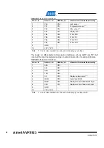
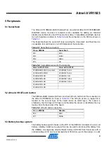
to measure the backup system power consumption a header with a mounted jumper
is available. The header is shown in
and is also marked with “VBAT” on
the silkscreen. The jumper can also be used to simulate battery insertion and removal
without actually removing the battery from the holder.
5.4 Mechanical buttons
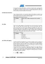
Three mechanical buttons are connected to Atmel AVR XMEGA. All buttons have
external pull-ups so there is no need to activate internal pull-ups in order to use them.
When a button is pressed it will drive the I/O line to GND.
Table 5-4.
Mechanical button connection.
Pin on XMEGA
Silkscreen text on PCB and designator in the schematics
PE5 SW0
PF1 SW1
PF2 SW2
5.5 LEDs
There are four LEDs available on the board that can be turned on and off. Two yellow
LEDs, one green LED (power indicator LED), and one red LED (status LED). The
green and red LEDs are inside the same package and therefore the colors can be
mixed to orange when both are activated. The yellow LEDs and the red LED can be
activated by driving the connected I/O line to GND. The green LED is controlled via a
FET and is by default on when the board is powered. However, this power indicator
LED can also be turned off by driving the gate of the FET to GND.
Table 5-5.
LED connections.
Pin on XMEGA
LED
PR0 Yellow
LED0
PR1 Yellow
LED1
PD4
Red status LED
PD5
Green power indicator LED
5.6 FSTN LCD display
The NHD-C12832A1Z-FSW-FBW-3V3 is a FSTN LCD display and has a resolution of
128 x 32 pixels. In the design the display is connected via a SPI based interface.
Detailed information about the display can be obtained from the display datasheet
(NHD-C12832A1Z-FSW-FBW-3V3 from New Haven Displays) and from the display
controller datasheet (ST7565R from Sitronix).
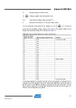
The external circuitry of the display is configured to boost the 3.3V supply voltage by
a factor of 3 to ~10V. However, the typical supply voltage of the display (contrast
control) is 6V and therefore the boosted supply must be adjusted, and this must be
done by software when the display is configured. The following formula is used when
the voltage is adjusted by software:
REG
V
Ra
Rb
V
⋅
⎟
⎠
⎞
⎜
⎝
⎛ −
⋅
⎟
⎠
⎞
⎜
⎝
⎛ +
=
162
1
1
0
α

