34
4317I–AVR–01/08
AT90PWM2/3/2B/3B
This clock may be selected as the system clock by programming the CKSEL Fuses as shown in
. If selected, it will operate with no external components. During reset, hardware loads
the pre-programmed calibration value into the OSCCAL Register and thereby automatically cal-
ibrates the RC Oscillator. The accuracy of this calibration is shown as Factory calibration in
By changing the OSCCAL register from SW, see
“Oscillator Calibration Register – OSCCAL” on
, it is possible to get a higher calibration accuracy than by using the factory calibration.
The accuracy of this calibration is shown as User calibration in
.
When this Oscillator is used as the chip clock, the Watchdog Oscillator will still be used for the
Watchdog Timer and for the Reset Time-out. For more information on the pre-programmed cali-
bration value, see the section
“Calibration Byte” on page 283
Notes:
1. The device is shipped with this option selected.
2. If 8 MHz frequency exceeds the specification of the device (depends on V
CC
), the CKDIV8
Fuse can be programmed in order to divide the internal frequency by 8.
When this Oscillator is selected, start-up times are determined by the SUT Fuses as shown in
.
Note:
1. If the RSTDISBL fuse is programmed, this start-up time will be increased to
14CK + 4.1 ms to ensure programming mode can be entered.
2. The device is shipped with this option selected.
Table 7-8.
Oscillator Calibration Register – OSCCAL
• Bits 7..0 – CAL7..0: Oscillator Calibration Value
The Oscillator Calibration Register is used to trim the Calibrated Internal RC Oscillator to
remove process variations from the oscillator frequency. The factory-calibrated value is automat-
ically written to this register during chip reset, giving an oscillator frequency of 8.0 MHz at 25°C.
The application software can write this register to change the oscillator frequency. The oscillator
can be calibrated to any frequency in the range 7.3 - 8.1 MHz within ±1% accuracy. Calibration
outside that range is not guaranteed.
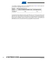
Table 7-6.
Internal Calibrated RC Oscillator Operating Modes
Frequency Range (MHz)
CKSEL3..0
7.3 - 8.1
0010
Table 7-7.
Start-up times for the internal calibrated RC Oscillator clock selection
Power Conditions
Start-up Time from Power-
down and Power-save
Additional Delay from
Reset (V
CC
= 5.0V)
SUT1..0
BOD enabled
6 CK
14CK
00
Fast rising power
6 CK
14CK + 4.1 ms
01
Slowly rising power
6 CK
14CK + 65 ms
10
Reserved
11
Bit
7
6
5
4
3
2
1
0
CAL7
CAL6
CAL5
CAL4
CAL3
CAL2
CAL1
CAL0
OSCCAL
Read/Write
R/W
R/W
R/W
R/W
R/W
R/W
R/W
R/W
Initial Value
Device Specific Calibration Value

