ATLO ATLO-FR-601 User Manual Download Page 4

5

6

6.3  Reader Mode

7.Sound and Light Indication

Light indicator

Operation Status

Buzzer

Beep—

Beep-Beep-Beep

Beep—
Beep
Beep—
Beep—
Beep—
Beep—

Beep—

Alarm

Red indicator flash slowly

Red

Green

Red indicator flash slowly

Orange
Green

Red indicator flash quickly

Stand by
Operation successful
Operation failed

Read card under card+facial mode
Read multi user cards
Enter programming mode
Enter setting status
Unlocking
Buzzer alarm

Read card under card+fingerprint mode

Press * key

Press digital key

Admin card exit programming

Admin card enter programming

8.Admin Menu

8.1 Standalone Mode Settings
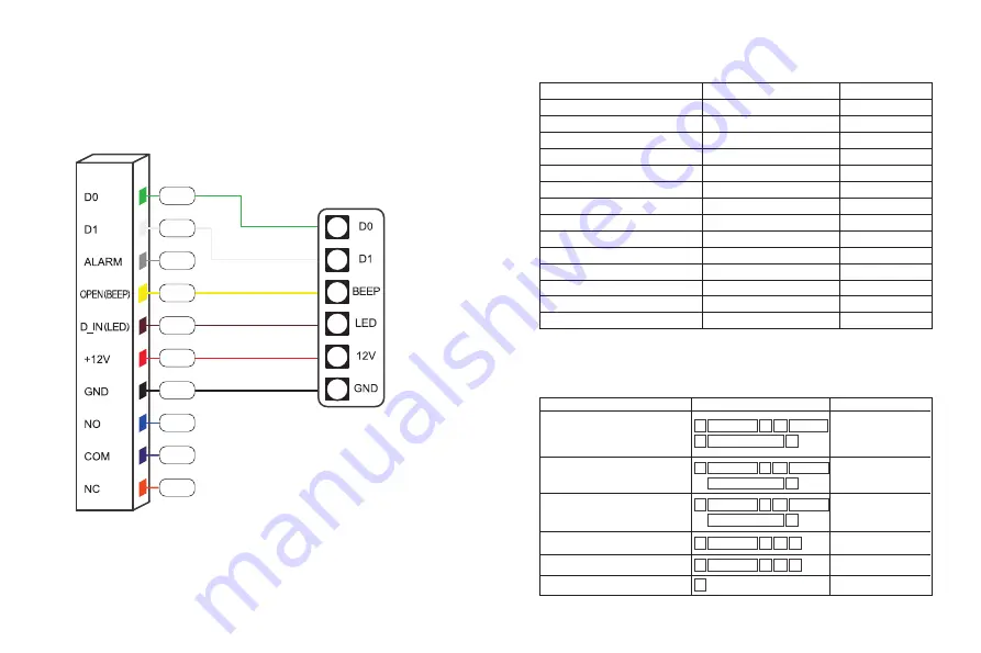
Device Management

Green

White

Yellow

Orange

Red

Blue

Access controller

Brown

Purple

Black

Grey

Function

Operation steps

Notes

Change Admin Code

Set Admin Add card or fingerprint

Set Admin delete card or fingerprint

Delete Admin Add card or fingerprint

Delete Admin Delete card or fingerprint

Exit Programming

Delete Admin Delete 

card or fingerprint

Delete Admin Add card 

or fingerprint

Press * to exit 

programming

To set Admin Delete 

card or fingerprint

To set Admin Add card 

or fingerprint

Factory Default Admin 

code is 999999.  This is 

the code when you reset 

the device to factory 

default

#

*

00 New code

Admin code

#

#

Repeat New code

#

*

*

02 Read card

Admin code

#

#

*

01

Admin code

#

#

*

*

02

Admin code

or 

Fingerprint 3 times

#

*

*

01 Read card

Admin code

or 

Fingerprint 3 times

Summary of Contents for ATLO-FR-601

Page 1: ...Facial Recognition Access Control User Manual With fingerprint Without fingerprint ...

Page 2: ...3 4 5 6 7 8 9 10 Wiegand input only when used as a reader Wiegand input only when used as a reader Alarm signal MOS tube drain output end optional Exit button input end Door contact switch input end Positive power supply or AC power supply end Negative power supply end Relay NO Relay COM Relay NC 4 Installation Remove the back cover from the keypad using the supplied special screw driver Drill 2 h...

Page 3: ...e Exit button Exit button Door contact Door contact Alarm Alarm Magnetic lock Magnetic lock 3 6 Diagram 4 6 1 Common Power Supply 6 2 Special Power Supply Note The door contact and alarm function are optional Note The door contact and alarm function are optional Brown Brown Purple Purple Black Black Grey Grey Special power supply ...

Page 4: ...mming 8 Admin Menu 8 1 Standalone Mode Settings Device Management Green White Yellow Orange Red Blue Access controller Brown Purple Black Grey Function Operation steps Notes Change Admin Code Set Admin Add card or fingerprint Set Admin delete card or fingerprint Delete Admin Add card or fingerprint Delete Admin Delete card or fingerprint Exit Programming Delete Admin Delete card or fingerprint Del...

Page 5: ...ete multiple users Delete card number Add multiple fingerprint user by specifying ID number Entry by Card Facial recognition Entry by card fingerprint Entry by specify user ID number then reading card and scanning face Entry by specify user ID number then reading card and inputting fingerprint User ID 1 50 2 10 users Delete all user cards faces and fingerprints Delete card fingerprint face user by...

Page 6: ...mming now After all the cards are added present the Admin Add card again You will hear long BEEP sound once and the indicator light turns red indicating that you have exited the Add card user programming mode Read admin add card Read the 1st user card Read the 2nd user card Read admin add card 9 10 3 0 Admin code 6 0 Admin code 6 1 Admin code 6 2 Admin code 8 0 Admin code 8 1 Admin code 8 2 Admin ...

Reviews: