


2/8
AtlasSound.com
TELEPHONE: (800) 876-3333
FAX (800) 765-3435
BlueBridge BBWP-TOUCH7
7" Touch Panel DSP Wall Controller Installation Guide
1601 JACK MCKAY BLVD.
ENNIS, TEXAS 75119 U.S.A.
©2013 Atlas Sound L
.P
. All rights reserved. Atlas Sound is a trademark of Atlas Sound L
.P
. All other trademarks are the property of their respective owners. All specs are subject to change without notice. P/N 4938
57 A
TS004748 RevA 10/13
2. The BBWP-TOUCH7 can be powered by two methods.
A. External 5V DC external power supply (included)
B. PoE network switch. Using a PoE switch is recommended as it will supply both power and network connectivity.
3. Choose the best location for the DC power cable and/or CATe5 cable to access the back can. There are
1
⁄
2
" knock outs on each side of the back
can to facilitate wire feeding.
4. Be sure the PoE or external power supply is disconnected on the opposite end of the cable ensuring no DC power is present in the cables.
5. Run the cable(s) through the back can.
6. Secure the back can to the surface using one of the screw slots provided.
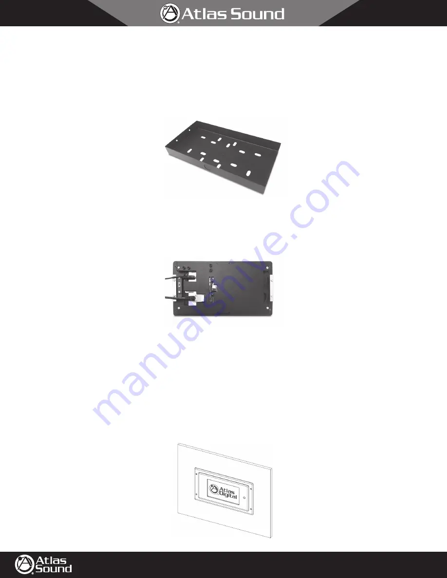
7. Connect the DC power and/or Ethernet CAT5e cable to the TOUCH7 as shown in Figure 05.
8. Carefully place assembly into back can, making sure no cables are pinched or kinked.
9. Continue to the "Powering Up" section on page 8.
In-Wall Mount
The BBWP-TOUCH7 can be flush mounted in a wall surface. There are two methods described below, Pre-Existing Construction and New
Construction. Each method has different requirements and steps for completion. In-wall mounting requires cutting a hole in the wall and running
CAT5e cable inside the wall from a PoE enabled Ethernet switch to the desired location of the TOUCH7. The BBWP-TOUCH7 comes with a bezel
dress ring plate and a separate back can for in-wall installation. In-wall installation will require the included bezel ring to cover any wall cutout
imperfections.
Figure 04
Figure 05
Power
Ethernet
Figure 06


