Step
Action
1
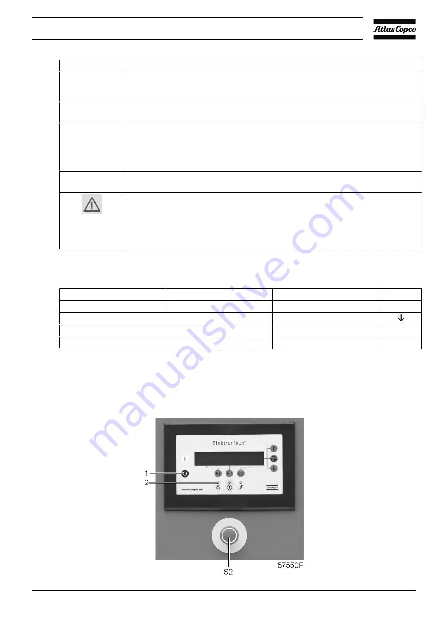
Daily check the display (2) for readings and messages. Normally, the main screen is shown
(see below), indicating the compressor outlet pressure, the status of the compressor and
the functions of the keys below the display.
2
Always check the display and remedy the trouble if alarm LED (3) is alight or blinks. See
“Elektronikon control system”
.
3
The display will show a service message if a service plan interval has been exceeded or
if a service level for a monitored component has been exceeded. Carry out the service
actions of the indicated plans or replace the component and reset the relevant timer.
Consult your Atlas Copco Customer Centre.
See also
“Preventive maintenance schedule”
.
4
Regularly check the actual compressor status by pressing the down key from the main
screen.
•
Before starting any maintenance or repairs, stop the compressor, wait until it has
stopped.
•
Close the air outlet valve and press the test buttons on top of the electronic water
drains to depressurize the air system.
•
Open the isolating switch (customer's installation) to switch off the voltage to the
compressor.
Example of the main screen
Compressor Outlet
7.0 bar
Automatically Loaded
Menu
Unload
F1
F2
F3
5.6
Stopping
Control panel
Instruction book
11
1
Summary of Contents for ZR-55
Page 12: ...General view of ZR 55 up to ZR 90 Full Feature with Energy Recovery Instruction book 11 ...
Page 13: ...Front view of ZR 55 up to ZR 90 Pack Instruction book 12 ...
Page 15: ...Views of ZT General view of ZT 55 up to ZT 90 Pack Instruction book 14 ...
Page 16: ...General view of ZT 55 up to ZT 90 Full Feature General view Instruction book 15 ...
Page 21: ...Flow diagram ZR Full Feature Instruction book 20 ...
Page 22: ...Flow diagram ZR Full Feature ND and ZR Full Feature with Low Load option Instruction book 21 ...
Page 23: ...Flow diagram ZT Instruction book 22 ...
Page 24: ...Flow diagram ZT Full Feature Instruction book 23 ...
Page 27: ...2 3 Condensate drain system Flow diagram ZR Instruction book 26 ...
Page 33: ...Flow diagram ZR Full Feature Instruction book 32 ...
Page 34: ...Flow diagram ZT Instruction book 33 ...
Page 41: ...Electric cabinet Typical example Typical example Instruction book 40 ...
Page 42: ...Drive motor M1 Drive motor M1 Instruction book 41 ...
Page 74: ...4 Installation 4 1 Dimension drawings Dimension drawing ZR Pack Instruction book 73 ...
Page 75: ...Dimension drawing ZR Pack with energy recovery Instruction book 74 ...
Page 76: ...Dimension drawing ZR Full Feature Instruction book 75 ...
Page 77: ...Dimension drawing ZR Full Feature with energy recovery Instruction book 76 ...
Page 78: ...Dimension drawing ZT Pack Instruction book 77 ...
Page 82: ...Installation proposal ZR Full Feature with energy recovery Instruction book 81 ...
Page 83: ...Installation proposal ZT Pack Instruction book 82 ...
Page 87: ...Instruction book 86 4 4 PANEL GA ZR 55 90 PACK ...
Page 88: ...Instruction book 87 ...
Page 89: ...Instruction book 88 ...
Page 90: ...Instruction book 89 ...
Page 100: ...Position of silica gel bags on ZT compressors Instruction book 99 ...
Page 102: ...Instruction book 101 ...
Page 122: ...7 2 Oil and oil filter change Control panel Oil system components ZR Instruction book 121 ...
Page 137: ...Instruction book 136 ...
Page 138: ...www atlascopco com ...


