


19
Instruction Manual
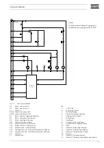
3.
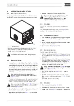
OPERATING INSTRUCTIONS
3.1
T
RANSPORT
INSTRUCTIONS
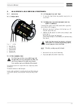
Strong, integrated beams (1) within the framework of the unit mean
that installation can be easily performed with use of a fork-lift truck.
Fig. 3.1
Integrated beams
Connecting the compressor to the prime mover is done by Atlas
Copco technicians. The same applies to any disconnecting.
Leave the cover in place during transport.
3.2
B
EFORE
STARTING
1. Remove the air receiver drain plug and open the drain valve (
, DV) to drain possible condensate. Close the valve when all
condensate has been drained or when oil comes out. Reinstall the
drain plug. The interval between draining operations may be
determined by experience, as the amount of condensate depends
on the operating conditions. It may be necessary to keep the side
panel(s) removed during operation to decrease the amount of
condensate.
2. Check the level of the compressor oil. The pointer of the oil level
gauge must register in the upper extremity of the green range.
Add oil if necessary. See section
for the oil to be used.
Normally, there is no need to add oil between two oil changes; if
there is, check the source of oil consumption.
3. Empty the dust trap of each air filter (
, AF). See section
.
4. Attach the air line(s) to the closed air outlet valve(s).
3.3
S
TARTING
Ascertain that the air receiver pressure is fully released before
starting.
Close the main switch and start the prime mover (
, PM)
according to the instructions of the manufacturer.
3.4
C
OMPRESSION
STARTING
1. When the prime mover is running smoothly, energize the loading
solenoid valve (
, LV) by pressing the loading push
button.
2. As soon as the unloading pressure registers on working pressure
gauge, the unit runs unloaded.
3. Open the outlet valve(s) (
, AOV).
3.5
D
URING
OPERATION
Regularly carry out following checks:
1. If the vacuum indicator switch (
, VIS) gives a warning
signal, stop the unit and service the air filters (
, AF). See
.
2. Check the compressor oil level. The pointer of the oil level gauge
must register in the upper extremity of the green range (
SG). If the level is too low, stop the unit and wait approx. 10
minutes to allow the air to escape from the oil. Add oil if
necessary. See section
for the oil to be used.
3. Check that the regulating valve (
, RV) is correctly
adjusted.
4. Check the air outlet temperatures of the compressor elements,
which are shown on the temperature gauges (
1
and
TG
2
).
Reinstall the side panel after checking.
3.6
S
TOPPING
1. Close the air outlet valve(s) (
, AOV).
2. Switch to noload condition and run the unit for some minutes.
3. Stop the prime mover (
, PM) and open the main switch.
Avoid knocks and violent shaking during transport.
Before draining the air receiver, ensure that the
pressure is released by opening the air outlet valve(s)
(
Before removing the oil filler plug (
, FP), ensure
that the pressure is released by opening the air outlet
valve(s) (
, AOV).
(1)
No external force may be applied to the air outlet
valve(s), e.g. by pulling hoses or by connecting
equipment directly to the valve(s) (e.g. a water
separator, a lubricator, pipe extensions, etc.).
Before removing the oil filler plug (
, FP) ensure
that the pressure is released by opening the air outlet
valve(s) (
, AOV).
Summary of Contents for ORV 10
Page 1: ...ORV 10 ORV 12 ORX 10 ORX 12 Instruction Manual for Portable Compressors English ...
Page 2: ......
Page 43: ......


