


Industrial Air Division
13
2920 5997 03
5. Gradually close the outlet valve while checking the air pressure
gauge. If the safety valve has not opened at the pressure
specified in section 7, it must be replaced by a new one. If the
compressor unloads before the specified opening pressure is
reached, repeat the procedure as mentioned from step 3.
6. Readjust the unloading pressure as described in sections 5.4.1
and 5.4.2.
7. Reconnect the hose or pipe to the closed air outlet valve.
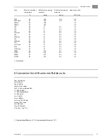
Switching-on pressure
→
bar(e)
Switching-on pressure
→
bar(e)
Switching-on pressure
→
bar(e)
LE5, -6
Switching-off pressure
→
bar(e)
LT530 up to -1230
Switching-off pressure
→
bar(e)
LT5, -6
Switching-off pressure
→
bar(e)
Example: LE5, -6
Stopping pressure: 7 bar(e)
Starting pressure: adjustable between 3.1 and 5.4 bar(e)
Example: LT5, -6
Stopping pressure: 16 bar(e)
Starting pressure: adjustable between 7 and 13 bar(e)
Figs. 7. Diagrams, pressure differential adjustment range
1.
Contact housing
2.
Adjusting screw for stopping pressure
3.
Adjusting screw for pressure difference
Fig. 8. Air pressure switch, type MDR4
F1755
Summary of Contents for LE11
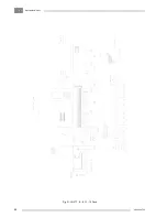
Page 22: ...IndustrialAirDivision 2920 5997 03 22 Fig 15 LE7 7N 8 8C LT7 8 730 Power Pack ...
Page 23: ...IndustrialAirDivision 23 2920 5997 03 Fig 16 LE9 9N 11 12 LT9 11 12 930 1230 Power Pack ...
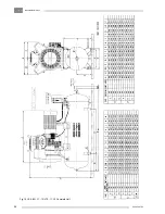
Page 24: ...IndustrialAirDivision 2920 5997 03 24 Fig 17 LE5 6 6C LT5 6 Complete Unit ...
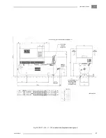
Page 25: ...IndustrialAirDivision 25 2920 5997 03 Fig 18 LE7 7N 8 8C LT7 8 Complete Unit ...
Page 26: ...IndustrialAirDivision 2920 5997 03 26 Fig 19 LE9 9N 11 12 LT9 11 12 Complete Unit ...
Page 28: ...IndustrialAirDivision 2920 5997 03 28 Fig 21 LE LT7 8 9 11 12 Pack ...


