


Instruction book
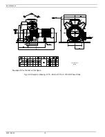
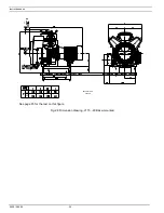
Fig. 1.8 Base-mounted
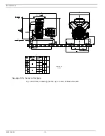
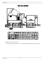
Fig. 1.9 LE/LF/LT with CD dryer
AC Air
cooler
AF Air
filter
AR Air
receiver
AV
Air outlet valve
CV Check
valve
Dm Condensate
drain
valve
FC Filler
cap
FN Fan
Gp
Air pressure gauge
M Motor
P1
Hourmeter, running time
SV Safety
valve
Y1
Loading solenoid valve
1 Cover
2 Blow-off
silencer
3
Air inlet silencer
4 Dewpoint
indicator
5 Cooling
pipe
6 Electric
cabinet
7 Unloader
8 Relief
valve
9
Pictograph, switch off voltage and
depressurize before maintenance or repair
10 LP cylinder
11 HP cylinder
12 DD filter
13 Air pressure switch with on/off switches
14 PD filter
15 CD dryer
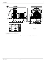
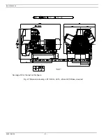
Figs. 1.4 up to 1.9 General views
1.1.1 Compressor variants
The
Compressor Block
(Fig. 1.1) includes:
-
Crankcase (4) and cylinders (6)
-
Air inlet filter (AF) and inlet silencer (3)
- Fan
(FN)
-
Air cooler piping (2) and (5)
-
Unloader (7, as standard on LE/LF/LT5 up to -10, LE15, -20 and LT15 up to -20)
-
Interstage relief valve (8, for LF7, -10, LE10 60 Hz, LE15, -20 and LT)
The
Power Pack
comprises (Figs. 1.2/1.3):
-
For LE/LF/LT2 and -3
: the Compressor Block as described above, with flanged-on electric motor (M), check
valve (CV-Fig. 1.4), and on 60 Hz air pressure switch with on/off switches (13-Fig. 1.4).
2920 1585 00
- 8 -