©2019 All Rights Reserved ▪ Atlantis Rail Systems, Micro Star and RailEasy is a
registered trademark and trademark of Suncor Stainless, Inc. ▪ www.atlantisrail.com
4
April 2019
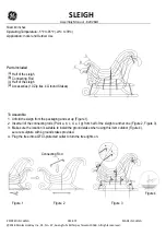
Connect each set of flexible LED light strip to the jumper
previously installed in each post (
See Figure K
). Once all of
the flexible LED light strip connections are made; make the
final connection to the transformer and plug it in to test.
Installing Lens Cover
Starting at one end of each of the aluminum channels, press
and fit the lens cover into place (
See Figure L
). When
installing the lens cover you will feel it being pressed into
place.
12 VOLT DC POWER SOURCE ONLY. MICRO STAR
LED LIGHT BARS ARE USED WITH DIRECT CURRENT
TRANSFORMERS ONLY. USING AN ALTERNATING
CURRENT TRANSFORMER OR A TRANSFORMER
OVER 12 VOLTS WILL CANCEL ALL WARRANTY
CLAIMS AND CAUSE THE LIGHTS TO BURN OUT
PREMATURELY.
DO NOT EXCEED 5 AMPS FOR A POWER SOURCE.
DO NOT USE AN AUTOMOTIVE, MARINE OR
MOWER BATTERY AS THIS MAY DAMAGE THE LED
LIGHT BARS. IF ANY ADDITIONAL WIRING AND
CONNECTIONS ARE REQUIRED, WIRE USING A
“PARALLEL” CIRCUIT. USING A “SERIES” CIRCUIT IS
NOT RECOMMENDED.
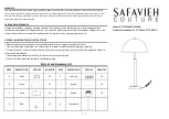
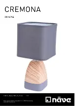
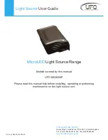
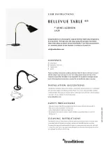
Figure O.
Male extension wiring for custom lengths and where jumper won’t fit
through post holes. Soldering or crimping required.
IT IS A GOOD IDEA TO CHECK THE LIGHTS ON-SITE
TO BE SURE THAT NO WIRING CAME LOOSE IN
TRANSIT.
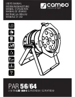
of the post so care should be taken in locating the centers.
Install the jumper (S0825-JMPR-SC) through each post (
See
Figure I
).
Installing Flexible LED Light Strip
Starting at one end of each of the aluminum channels press
and fit into place the flexible LED light strip into the channel
(
See Figure J
).
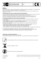
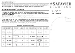
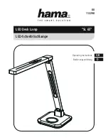
Figure I.
(LEFT)
Install the jumper (S0825-JMPR-SC) through each post.
Figure J.
(RIGHT)
Press and fit into place the flexible LED light strip into the
channel.
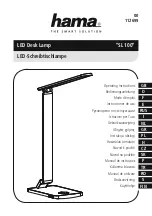
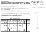
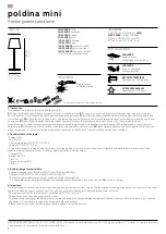
Figure K.
(LEFT)
Connect each set of flexible LED light strip to the jumper
previously installed in each post.
Figure L.
(RIGHT)
Starting at one end of each of the aluminum channels,
press and fit the lens cover into place.
Additional Components
Micro Star Jumper (12”) - (S0825-JMPR-SC)
Screw connector male / female to go through 4”x4” posts (
See
Figure M
).
Micro Star Extension Wiring (8”) - (S0825-JF08-SC)
Female extension wire for custom lengths and where jumpers
won’t fit through post holes (
See Figure N
).
Micro Star Extension Wiring (8”) - (S0825-JM08-SC)
Male extension wire for custom lengths and where jumpers
won’t fit through post holes (
See Figure O
).
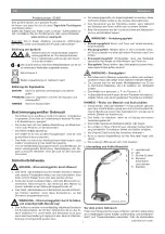
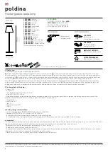
Figure M.
Jumper to go through 4”x4” posts and connect wire harnesses and
Micro Star lights.
Figure N.
Female extension wiring for custom lengths and where jumper won’t
fit through post holes. Soldering or crimping required.