Technical Manual & Parts Lists
12
Touch Screen Operation
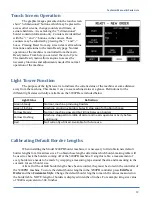
The graphic images presented on the touch screen
show “3-dimensional” buttons, which may be pressed to
access other screens, change counters and timers, or
actuate hardware. Areas lacking the “3 dimensional”
border contain information only. Counters are identified
with the “+” and “-” buttons in the corners. These
counters may be adjusted by pressing the “+” and “-”
boxes. Pressing Reset from any screen clears all machine
functions and returns to the main Ready page. Normal
operation of the machine is controlled from the main
Ready menu. From here you can start the Auto Cycle.
The main Ready menu allows anyone to access the
necessary functions and adjustments needed for normal
operation of the machine.
Light Tower Function
The purpose of the light tower is to indicate the current status of the machine at some distance
away from the machine. This makes it easy to see machine status at a glance. Definitions for the
different light states currently available on the 3200PB are included below.
Light Status
Definition
Green Steady
Normal, machine producing borders
Green Flashing
Machine producing borders but will stop soon for bobbin change.
Yellow Steady
Normal, machine powered but idling between borders.
Yellow Flashing
Machine stopped in middle of order and needs operator activity before
continuing.
Red
Not currently utilized. Available for future use.
Calibrating Default Border Lengths
When installing the Model 3200PB border machine, it is necessary to first obtain new default
border lengths for all mattress sizes. To obtain these lengths determine which border-making table will
be used to check the borders coming off of the 3200PB machine. Using this table, a measurement of
every border size needs to be made by wrapping a measuring tape around the arm and measuring to the
cut mark for each border size.
After all of the default border lengths have been recorded, they must be stored in the controller of
the 3200PB1 machine. To store the default border lengths in the 3200PB controller press
Edit New
Order
and then
Customize Style
. Change the default border lengths to match the values measured on
the border table. NOTE: length of borders is displayed in tenths of inches. For example: king size value
of 3040 is equivalent to 304.0 inches
Summary of Contents for 3200PC
Page 2: ......
Page 16: ...Technical Manual Parts Lists 11 Component Identification Power and Air supply hookups ...
Page 26: ...Technical Manual Parts Lists 21 ...
Page 30: ...Technical Manual Parts Lists 25 ...
Page 32: ...Technical Manual Parts Lists 27 ...
Page 34: ...Technical Manual Parts Lists 29 ...
Page 36: ...Technical Manual Parts Lists 31 ...
Page 38: ...Technical Manual Parts Lists 33 ...
Page 40: ...Technical Manual Parts Lists 35 ...
Page 42: ...Technical Manual Parts Lists 37 ...
Page 44: ...Technical Manual Parts Lists 39 ...
Page 46: ...Technical Manual Parts Lists 41 ...
Page 48: ...Technical Manual Parts Lists 43 ...
Page 50: ...Technical Manual Parts Lists 45 ...
Page 52: ...Technical Manual Parts Lists 47 ...
Page 54: ...Technical Manual Parts Lists 49 ...
Page 56: ...Technical Manual Parts Lists 51 ...
Page 57: ...Technical Manual Parts Lists 52 32007600P Transport Assembly AAC Drawing Number 192087A Rev5 ...
Page 58: ...Technical Manual Parts Lists 53 ...
Page 60: ...Technical Manual Parts Lists 55 ...
Page 62: ...Technical Manual Parts Lists 57 ...
Page 65: ...Technical Manual Parts Lists 60 3200PC PD Pneumatic Diagram 125621B ...
Page 66: ...Technical Manual Parts Lists 61 3200PC WD Wiring Diagram Control panel 125622B ...


