background image

Technical Manual & Parts Lists 

84 


3200PME Marking Module, Miter 

AAC Drawing Number   9000645   Rev 1 


NO. QTY PART #

DESCRIPTION

NO. QTY PART #

DESCRIPTION

1

1

3200302

PEN CAP

13

3

NNH10-32

#10-32 HEX NUT

2

1

3200303

PLATE, CAM

14

1

SSAS016024

1/4 X 3/8 X 10-24 SHLD, BOLT

3

1

3200304

MOUNTING BRKT.

15

1

SSAS016064

1/4 X 1 X 10-24 SHLD, BOLT

4

1

3200305

BRACKET, CYL ROD MOUNT

16

1

SSFC90024

#8-32 x 3/8 FLAT ALLEN

5

1

3200312

GUIDE PIN, THREADED

17

2

SSFC90048

#8-32 X 3/4 FLAT ALLEN

6

1

3200PM-3001 HOLDER, PIN

18

2

SSSC90048

#8-32 X 3/4 SOC CAP

7

2

AA198RA510

FLOW CONTROL,5/32X10-32

19

2

UUAA347-02

BEARING,BRONZE,.2515ID

8

1

AAC8D-2

CYLINDER, AIR

20

1

UUAA347-03

BEARING,BRONZE,.2515ID

9

1

BBTRA411

WASHER,THRUST,STEEL

21

2

WWF8

WASHER, FLAT #8

10

1

MM6844K32

PLUG, 3/8 NPT

22

2

WWL8

#8 LW

11

1

MM94115K204 O'RING, 1/8 X 3/8 X 5/8

23

1

ZZZSR-200

SHARPIE MARKER, BLACK

12

2

NNH10-24

#10-24 HEX NUT

Summary of Contents for 1335MFB

Page 1: ...Atlanta Attachment Company 362 Industrial Park Drive Lawrenceville GA 30046 770 963 7369 www atlatt com Technical Manual Parts Lists Model 1335MFB Revision 9 1 Updated May 12 2016 ...

Page 2: ......

Page 3: ...erials contained herein are additionally protected by United States Copyright law and may not be used disclosed reproduced distributed published or sold without the express written consent of Atlanta Attachment Company which consent may be withheld in Atlanta Attachment Company s sole discretion You may not alter or remove any copyright trademark or other notice from copies of these materials IMPO...

Page 4: ...c Machine Operation 22 Loading the Gusset Roll and Unwinder 22 Loading and Adjusting the Folder 23 Adjusting the Edge Guide 23 Loading the Panel and Border Gusset 23 Sewing the Panel with Rounded Corners 23 Sewing the Panel with Straight Corners 23 Adjusting the Corner Ruffles 24 Adjusting the Corner Stop Count 24 Finishing the Panel 24 Sewing in Border Mode 24 Efka Control Box Settings 24 Initial...

Page 5: ...or Assembly 54 1335505 Stripper Blade Assembly 56 1335530 Base Console Assembly 58 1335575 Roll Holder Assembly 60 1335659 Guide Roller Assembly 62 1335674 Encoder Assembly 64 1335690 Cylinder Lift Assembly 66 1335695 Ruffler Assembly 68 1335750 Puller Assembly 70 1335778 Sew Head Assembly 72 1335779 Base Console Assembly 74 1335M 2300B Pivot Assembly 76 3200PMD Marking Module Assembly 78 A 2216W5...

Page 6: ... A list of recommended spare parts Instruction Manual s for components made by other manufacturers The layout and installation diagram containing information for installation Intended Use Our machines are designed and built in line with the state of the art and the accepted safety rules However all machines may endanger the life and limb of their users and or third parties and be damaged or cause ...

Page 7: ... work on the machine is only carried out by reliable persons who have been appropriately trained for such work either within the company by our field staff or at our office and who have not only been duly appointed and authorized but are also fully familiar with the local regulations Work on the machine should only be carried out by skilled personnel under the management and supervision of a duly ...

Page 8: ...airing safety are observed in the machine or its mode of operation such as malfunctions faults or changes in the machine or tools appropriate steps must be taken immediately the machine switched off and a proper lockout tagout procedure followed The machine should be examined for obvious damage and defects at least once per shift Damage found shall be immediately remedied by a duly authorized pers...

Page 9: ...ny obstructions whatsoever is essential for safe operation of the machine The floor should be level and clean without any waste The workplace should be well lit either by the general lighting or by local lights Emergency STOP The emergency STOP buttons bring all machine movements to a standstill Make sure you know exactly where they are located and how they work Try them out Always ensure easy acc...

Page 10: ... so that it cannot be switched on again without authorization In practice this may mean that the technician electrician and operator all attach their own padlock to the master switch simultaneously so that they can carry out their work safely Locking extension plates should be available for multiple locks if required The primary purpose for a lockout tagout procedure is to protect workers from inj...

Page 11: ...hen transporting the machine or assemblies in a crate ensure that the ropes or arms of a forklift truck are positioned as close to the edge of the crate as possible The center of gravity is not necessarily in the middle of the crate Note the accident prevention regulations safety instructions and local regulations governing transport of the machine and its assemblies Only use suitable transport ve...

Page 12: ... Do not use any corrosive cleaning agents Use lint free rags Retighten all screw connections that have to be loosened for the maintenance and repair work Any safety mechanisms that have to be dismantled for setting up maintenance or repair purposes must be refitted and checked immediately after completing the work Maintenance Care Adjustment The activities and intervals specified in the Instructio...

Page 13: ...fault develops in the electrical power supply The electrical equipment of our machines must be checked at regular intervals and any defects found must be remedied immediately If it is necessary to carry out work on live parts a second person should be on hand to operate the emergency OFF switch or master switch with voltage release in the event of an emergency The working area should be cordoned o...

Page 14: ...ating this equipment It is also the owner s responsibility to make certain that the operator is a qualified and physically able individual properly trained in the operation of this equipment Specific safety warning decals are located on the equipment near the immediate areas of potential hazards These decals should not be removed or obliterated Replace them if they become non readable ALWAYS keep ...

Page 15: ...atic 70 80 PSI 2 SCFM avg Sewing Head Yamato VM1804P Sewing Speed 3500 RPM Needle Standard SN62X5721 Stitch Density 6 SPI Installation Setup Provide a 220VAC single phase 5 Amp electrical drop and 1 4 air supply line 80 PSI Remove any shipping straps from machine Mount and adjust the Guide Roller Assembly Check the oil level in the oil pan ...

Page 16: ...lock allows access to a screen for setting the correct time and date There are also ADVANCED settings and functions available These functions are only accessible by a password and include timers that control machine hardware input and output test screens and machine statistics To get to the advanced functions the appropriate password must be entered at the security screen Security access is reset ...

Page 17: ...een without resetting the machine Back on the main screen press the SETUP button to access the setup screen This allows setup of the ruffle quantity and stitches access to SECURITY SYSTEM INFORMATION ADVANCED SETUP and the SHOW ALL SETTINGS matrix screen The CONTRAST button changes the screen contrast The and buttons change the counters ...

Page 18: ...NCED SETUP screens Note when a button has a white background the function is on or enabled A dark background indicates off or disabled Press the top arrows to return to the first SETUP screen Press the PANEL MODE button to change the machine to the Panel Sewing mode In this mode panel edge detection and corner stitch counting are enabled The length and corner markers are disabled ...

Page 19: ...electing the corner mode When the ROUND CORNER button has a WHITE background the machine is in the ROUND CORNER mode When the background is DARK the machine is in the STRAIGHT CORNER mode The SYSTEM INFORMATION screens displays serial numbers lifetime counter and company info Press EXIT to return to SETUP screen The SECURITY screen allows you to change the access code for the ADVANCED functions ...

Page 20: ...ing is the same setting as the RUFFLE ENABLE button on SETUP BORDER MODE page 2 mentioned earlier The same is true for many of the other settings shown The Encoder Compensation setting is used to calibrate the measuring wheel for proper length measurement and is already calibrated Do not alter this setting The Corner Marker Distance setting has been set to place the corner marks in their proper po...

Page 21: ...minimum run time of the unwinder motor after the loop eye activates the motor Thread Det Time is a delay of the thread break detectors to allow the sewing head to come to full speed before the detectors look at the thread The Panel Mode Border Mode button switches the machine mode and the STOP COUNT button adjust the CORNER STOP COUNT the same as the buttons in the SETUP screens above Press the to...

Page 22: ...age and enable the foot switches for manual sewing and foot lift functions You can turn on the ruffle cycle for testing and access the advanced manual pages for testing inputs and outputs Press the PIECE COUNT button to access a screen for resetting the daily piece counter ...

Page 23: ...e to a different size border and edit the size settings Use the Border Quantity button to set the number of borders to be run consecutively without stopping Press SELECT NEW STYLE to change sizes Select the desired style and the machine will return to the EDIT ORDER screen ...

Page 24: ...ical Manual Parts Lists 19 Press EDIT STYLES to input or change the styles menu The top arrows take you to additional screens Select the button for the style you wish to edit or create Example select style 5 ...

Page 25: ...rder length equals the bed length times 2 plus the bed width times 2 plus the seam allowance times 2 Example For a bed that is 78 long and 36 wide and has a seam allowance of the border length is 78 78 36 36 229 The numbers can be adjusted as needed to get the best fit on the bed The 1st CORNER distance is set the same way and is equal to one half of the bed width plus one seam allowance Example I...

Page 26: ...e problem Machine Operation Turn on the main power circuit breaker item 1 with lockout located inside the control cabinet Turn on the machine by pressing the green on button item 2 located above the touch screen panel Be sure the red emergency stop button is released After a moment the main screen will appear and the green status LED will be blinking Refer to these instructions for detailed touch ...

Page 27: ...eedle down at neutral treadle and needle up after full heal back The functions can be changed upon power up or after a full heal back The control box has been preprogrammed to operate with the Ruffler If the box were replaced the new box would need to be programmed according to the included parameter list in order to function properly Notice that the sewing head does not stop at normal needle up l...

Page 28: ...ewing the Panel with Rounded Corners Go to the SETUP PANEL MODE screen and set the ROUND CORNER button so it has a WHITE background indicating ROUND CORNER mode Set the Ruffles per Corner Stitches per Ruffle and Stop Count as desired Return to the Main screen Sew the panel all the way to corner being sure not to get your hands in the way of the electric eye mounted under the table that must see th...

Page 29: ...ailing edge of the border overlaps the starting point Stop raise the folder cut the border and swing out the folder and stripper blade Remove the panel from the machine Mark and close the border so it fits the panel Place the border and panel back under the presser foot and join the unsewn portion of the panel to the closed portion of the border Sewing in Border Mode Sew in Border Mode when making...

Page 30: ...under the foot while ruffling The Efka motor should be set for stopping needle down at neutral treadle to help hold the ruffle in place while turning the corners The auxiliary foot pressure cylinder should be set to provide added foot pressure while sewing straight Ruffler Drive Set the Ruffler blade position left to right The slot in the Ruffler blade should align with the sewing needle Loosen th...

Page 31: ...ck all belts for tightness and condition Adjust or replace as necessary Check oil level in oil pan Put one drop of machine oil on all moving Ruffler parts Electric Eye Sensor Adjustment To adjust the sensor first remove the clear plastic cover from the end of the sensor There are two adjusting screws under the cover One is labeled GAIN and is used to set the sensitivity of the sensor The other scr...

Page 32: ...Technical Manual Parts Lists 27 Parameter Settings for Efka Controller ...

Page 33: ...Technical Manual Parts Lists 28 1335M Folder Spacer Reference Chart ...

Page 34: ...Technical Manual Parts Lists 29 ...

Page 35: ...a Attachment Company In addition to any confidentiality and non disclosure obligations that currently exist between you and Atlanta Attachment Company your use of these materials serves as an acknowledgment of the confidential and proprietary nature of these materials and your duty not to make any unauthorized use or disclosure of these materials ...

Page 36: ...Technical Manual Parts Lists 31 ...

Page 37: ...CRIPTION 1 1 1335530 BASE CONSOLE SBUS 2 1 1335575 ROLL HOLDER ASBLY NS AR 1335MFB18 PD PNEUMATIC DIAGRAM NS AR 1335MFB18 WD WIRING DIAGRAM 5 1 3200PMD MARKING MODULE EXT MOUNT 6 1 4059 FP301D FOOT PEDAL ASSY EFKA 7 1 A 2216V5 8 FOLDER CONT W GUSSET Page 78 Page Page 60 Page Page 58 Page Page 85 Page Page 87 Page ...

Page 38: ...Technical Manual Parts Lists 33 ...

Page 39: ...1335779 BASE CONSOLE SBUS NS AR 1335MFB PD PNEUMATIC DIAGRAM NS AR 1335MFB WD WIRING DIAGRAM 6 1 3200PMD MARKING MODULE EXT MOUNT 7 1 4059 FP301D FOOT PEDAL ASSY EFKA 8 1 A 2216W56 FOLDER CONT W GUSSET 9 2 NNK5 16 18 KEP NUT 5 16 18 10 2 SSHC10176 5 16 18 X 2 3 4 HEX HEAD 11 4 WWFS5 16 WASHER FLAT 5 16 Page 36 Page Page 60 Page Page 74 Page Page 86 Page Page 88 Page Page 78 Page Page 80 Page ...

Page 40: ...Technical Manual Parts Lists 35 ...

Page 41: ...EX HEAD 23 1 1335864 BRACKET CYLINDER 72 6 SSHC10064 5 16 18 X 1 HEX HEAD 24 2 1335908 PLATE BORDER DEFLECTOR 73 1 SSHC10096 5 16 18 X 1 1 2 HEX HEAD 25 1 1335M 2046 PLATE NUT 8 32 43 CTC 74 2 SSHC10128 5 16 18 X 2 HEX HEAD 26 1 1335M 4007 COVER BELT 75 2 SSHC10176 5 16 18 X 2 3 4 HEX HEAD 27 1 1347097 SUPPORT TENSIONER 76 4 SSHC25112 3 8 16 X 1 3 4 HEX HEAD 28 2 1349381 ROD STRAIGHT CRS 77 4 SSPS...

Page 42: ...Technical Manual Parts Lists 37 ...

Page 43: ...OT 17 1 1335M 2034 PLATE NUT 2 56 55 1 SSPS50032 2 56 X 1 2 PAN HD SLOT 18 1 1335M 2035 ADJUSTMENT NUT 10 32 56 1 SSPS50048 2 56 X 3 4 PAN HD SLOT 19 1 1335M 2036 SUPPORT BLOCK 57 5 SSSC01032 1 4 20 X 1 2 SOC CAP 20 1 1335M 2037 WASHER STOP 58 1 SSSC85024 6 40 X 3 8 SOC CAP 21 1 1335M 2038 STOP WASHER 59 2 SSSC90024 8 32 X 3 8 SOC CAP 22 1 1335M 2039 NUT SPRING RETAINER 60 4 SSSC90032 8 32 X 1 2 S...

Page 44: ...Technical Manual Parts Lists 39 ...

Page 45: ...CYL MOUNT 6 1 1335M 2034 PLATE NUT 2 56 7 1 1335M 3008A MTG BRKT SENSOR 8 2 AA198RA510 FLOW CONTROL 5 32X10 32 9 1 AAC8DP 5 CYL AIR DA 9 16 B 1 2S 10 1 AAFBP 8C BRKT PIVOT 5 32 BORE 11 1 NNH10 32 10 32 HEX NUT 12 1 SSPS50032 2 56 X 1 2 PAN HD SLOT 13 4 SSSC01032 1 4 20 x 1 2 LG SHCS 14 1 SSSC01048 1 4 20 X 3 4 SOC CAP 15 2 SSSC90024 8 32 X 3 8 SOC CAP 16 2 SSSC98048 10 32 X 3 4 SOC CAP 17 1 WWF2 W...

Page 46: ...Technical Manual Parts Lists 41 ...

Page 47: ...BRKT FOOT LIFT 2 1 1335M 108 LEVER 3 1 AA198RR508 FLOW CONTROL 5 32 X 1 8 4 1 AAC7DP 5 CYLINDER AIR DA 5 1 AAFBP 11C BRKT PIVOT 1 4 BORE 6 1 AAFCT 7 CLEVIS AIR CYL 1 4 28 7 1 AAFP18 MUFFLER 1 8 NPT BRONZ 8 1 NNJ1 4 28 1 4 28 HEX JAM NUT 9 1 SSAS020016 SHOULDER BOLT 1 4 X 1 4L 10 2 SSSC98024 10 32 X 3 8 Lg SHCS 11 2 WWLM6 M6 LOCK WASHER ...

Page 48: ...Technical Manual Parts Lists 43 ...

Page 49: ...18 1 AA198RR510 REV FL CONT 5 32X10 32 19 1 AAC024DXP CYL BIMBA 9 16 B 4 S 20 1 AAC8DP 1 5 CYL AIR DA 9 16B 2S 21 2 AAFBP 8C BRKT PIVOT 5 32 BORE 22 2 BBAW 3Z BRG ROD END F 10 32 23 2 CCCL3F CLAMP COLLAR 3 16 24 3 MMGN12HZ0HN MGN12H BEARING BLOCK 25 2 MMGNR12R0165HN 165MM RAIL MGN12H BLK 26 1 MMGNR12R090HN 12MM X 90MM RAIL 27 1 NNH10 32 10 32 HEX NUT 28 1 NNJ10 32 NUT JAM THIN 10 32 29 2 NNW10 32 ...

Page 50: ...Technical Manual Parts Lists 45 ...

Page 51: ...35 9 SOLENOID ASSY 9 STATION 13 1 EECA491024 CONTACTOR MINI 240V 14 44 EEDC2X2 COVER WIRE DUCT 15 44 EEDF2X2 DUCT WIRE 2X2 MOD 16 2 FF264 3BKT2 MOUNT WAGO 2 LONG 17 2 FF264 3BKT2 5 MOUNT WAGO 2 LONG 18 10 FF264 341 TERMBLK WAGO TOP DUAL GRY 19 4 FF264 347 TERMBLK WAGO TOP DUAL GRN 20 4 FF264 371 TERMBLK WAGO TOP END 21 8 FF1724 STRAIN RELIEF 22 2 FFD2425F RELAY SSR 24VAC 25A 23 1 FFRAV781BW MODULE...

Page 52: ...Technical Manual Parts Lists 47 ...

Page 53: ...E NEEDLE 1N 20 1 54242B9016 SPREADER 9NDL 1 4 GA 21 1 AAFCT 7 CLEVIS AIR CYL 1 4 28 22 2 AAQME 5 8 QUICK MALE ELBOW 23 1 AAV41 P HUMPHREY VALVE 4 WAY 24 1 M1V67 016 FOOT 1N RUFFLER 25 1 MM4554K11 PLUG 1 8 PIPE 26 1 NNJ1 4 28 1 4 28 HEX JAM NUT 27 2 SSBC80024 6 32 X 3 8 BUT HEAD 28 2 SSFC80024 6 32 X 3 8 FLAT ALLEN 29 1 SSFCM6X12 M6 1 0 X 12 FLAT ALLEN 30 2 SSHC98032 10 32 X 1 2 HEX HEAD SS 31 2 SS...

Page 54: ...Technical Manual Parts Lists 49 ...

Page 55: ...48D BRACKET PULLER LIFT HD 2 1 AAC6DX 1 5 CYLINDER AIR DA PIVOT 3 1 AAFBP 11C BRKT PIVOT 1 4 BORE 4 1 AAFCT 11 CLEVIS CYL 5 16 24 1 4 5 1 AAFP18 MUFFLER 1 8 NPT BRONZ 6 1 AAQME 5 8 QUICK MALE ELBOW 7 1 CCCL5F CLAMP COLLAR 5 16 BORE 8 2 NNH1 4 20 1 4 20 HEX NUT 9 1 NNJ5 16 24 5 16 24 HEX JAM NUT 10 2 SSSC01032 1 4 20 X 1 2 SOC CAP ...

Page 56: ...Technical Manual Parts Lists 51 ...

Page 57: ...R PLATE 8 1 1335929 STRIPPER PLATE 9 1 3100612 UPPER FEED ROLLER YOKE GU 10 18 BBTRA815 WASHER THRUST STEEL 1 2 11 3 WWS307 1 WASHER SPRING BELVEL 12 1 SSSC05040 1 4 28 X 5 8 SOC CAP 13 1 SSSC20080 5 16 24 X 1 1 4 SOC CAP 14 1 WWL1 4 1 4 LW 15 1 WWL5 16 5 16 LW 16 2 NNJ1 4 28 1 4 28 HEX JAM NUT 17 2 SSBC90016 8 32 X 1 4 BUT HEAD 18 2 SSFC80024 6 32 X 3 8 FLAT ALLEN 19 2 SSSC90032 8 32 X 1 2 SOC CA...

Page 58: ...Technical Manual Parts Lists 53 ...

Page 59: ... 2 HEX HEAD NS AR 1335MFB PD DIAGRAM PNEUMATIC 63 8 SSHC01048 1 4 20 X 3 4 HEX HEAD NS AR 1335MFB WD DIAGRAM WIRING 64 1 SSHC10048 5 16 18 X 3 4 HEX HEAD NS 1 1335MFBCAB CABLE PACKAGE 65 3 SSHC10096 5 16 18 X 1 1 2 HEX HEAD 23 1 1338 018 SPACER HEAD 66 10 SSPP98024 10 32 X 3 8 PAN HD PHIL 24 1 4059 DC1500 MOTOR CONTROLLER 67 4 SSPS70048 4 40 X 3 4 PAN HD SLOT 25 1 4080 4508B CABLE STEP MOTOR 68 2 ...

Page 60: ...Technical Manual Parts Lists 55 ...

Page 61: ...TA613 BEARING THRUST 375BORE 10 4 BBTRA613 WASHER THRUST STL 375B 11 2 CCSC6F3_8 COLLAR SET 3 8 12 1 NNE5 16 18 NUT ELASTIC LOCK 5 16 18 13 1 NNJ3 8 16 3 8 16 JAM NUT 14 1 NNW1 4 20 NUT WING 1 4 20 15 1 SSAS024128 SHULDER BOLT 3 8 X 2 0L 16 2 SSBC95040 10 24 X 5 8 BUTTON CAP SC 17 2 SSBC98024 10 32 X 3 8 BUTTON CAP SC 18 2 SSFC90024 8 32 X 3 8 FL ALN CAP 19 1 SSMB58N PLUNGER BALL 3 8 16X5 8L 20 2 ...

Page 62: ...Technical Manual Parts Lists 57 ...

Page 63: ...KET 3 1 26151 TOOL TRAY 1X3 5X9 4 1 1335258 RUFFLER ASSY YAM VM1804P 5 1 1335425 SEW HEAD SUBASSEMBLY 6 1 1335463 STAND MOTOR ASBLY 7 1 1959 112 2 POS THREAD PLATE ASSY 8 2 4003 IS3WT2 SENSOR THREAD BREAK 9 4 WWFS1 4 WASHER FLAT 1 4 10 4 WWL1 4 1 4 LW 11 1 ZX3833 V BELT 3 8 X 33 12 4 SSSC01040 1 4 20 X 5 8 SOC CAP 13 4 SSSC01064 1 4 20 X 1 SOC CAP Page 48 Page Page 38 Page Page 54 Page ...

Page 64: ...Technical Manual Parts Lists 59 ...

Page 65: ...3 1 265155A HOLDER EYE 1 2 BORE 4 4 28201 BLOCK CROSS LARGE 5 1 28201B LARGE PIVOT BLOCK 6 2 786B12 2 2 DISC CONE BEARING ASSY 7 1 8732 0736 ROD ST CRS 1 2 X 11 5 8 3 8748 0512 ROD STRA CRS 3 4X8 9 1 FFQM42VN6A EYE ELECTRIC 10 30VDC 10 2 SSPS50048 2 56 X 3 4 PAN HD SLOT 11 1 SSSC98040 10 32 X 5 8 SOC CAP 12 1 TTH32426 HANDLE THRD 5 16 18X1 1 4 13 2 WWF4 WASHER FLAT 4 14 2 WWL4 4 LW ...

Page 66: ...Technical Manual Parts Lists 61 ...

Page 67: ...YLINDER RODEND 34 1 SSHC01080 1 4 20 X 1 1 4 HHCS 11 1 1335683 BAR STIFFENER 35 1 SSHC01192 HEX HEAD BOLTS 1 4 20 X 12 1 1335684 MOUNT SENSOR 36 4 SSPS98032 10 32X1 2 PAN HD SLOT 13 1 273 4 503 WASHER LEATHER 37 4 SSSC90048 8 32 X 3 4 SOC CAP 14 2 A 2216D65 GUIDE LEFT FOLDER 7 8 38 4 SSSC98048 10 32 X 3 4 SOC CAP 15 1 A 2216D66 T NUT 39 1 SSSC98080 10 32 X 1 1 4 SOC CAP 16 2 AA198RA508 FLOW CONTRO...

Page 68: ...Technical Manual Parts Lists 63 ...

Page 69: ... 14 4 BBTRA411 WASHER THRUST STEEL 15 2 BBTT601 WASHER THRUST BRONZE 16 1 EEH1 096 HS ENCODER OPTICAL 17 1 EEPC3 MODULE ENCODER 18 1 NNE1 4 20 NUT ELASTIC LOCK 1 4 20 19 1 NNH1 4 20 NUT HEX 1 4 20 20 3 NNH10 24 HEX NUT 10 24 REG 21 2 NNK1 4 20 KEP NUT 1 4 20 22 1 RRBEEHIVEH SPRING HEAVY BEEHIVE 23 2 SSPP80024 6 32X3 8 PAN PHILLIPS 24 1 SSPP90024 8 32X3 8 PAN PHLPS 25 4 SSPS98016 10 32 X 1 4 PAN HD...

Page 70: ...Technical Manual Parts Lists 65 ...

Page 71: ...L CONT 5 32X10 32 18 1 AAC7DP 4 CYLINDER AIR DA 19 1 AAC8DP 1 CYL AIR DA 9 16B 1S 20 1 AAFBP 8C BRKT PIVOT 5 32 BORE 21 1 AAFCT 7 CLEVIS AIR CYL 1 4 28 22 1 BBAW 3Z BRG ROD END F 10 32 23 1 CCCL3F CLAMP COLLAR 3 16 24 1 CCCL4F COLLAR 1 4 CLAMP 25 1 CCSC41 4 COLLAR SET 1 4 26 3 MMGN12HZ0HN MGN12H BEARING BLOCK 27 2 MMGNR12R0165HN 165MM RAIL MGN12H BLK 28 1 MMGNR12R76HN 76MM RAIL MOD 29 1 NNH10 32 1...

Page 72: ...Technical Manual Parts Lists 67 ...

Page 73: ...LUNGER BALL 3 8 16X5 8L 16 1 1335M 2034 PLATE NUT 2 56 51 2 SSPS50020 2 56 X 5 16 PAN HD SLOT 17 1 1335M 2035 ADJUSTMENT NUT 10 32 52 1 SSPS50032 2 56 X 1 2 PAN HD SLOT 18 1 1335M 2036 SUPPORT BLOCK 53 1 SSPS50048 2 56 X 3 4 PAN HD SLOT 19 1 1335M 2037 WASHER STOP 54 6 SSSC01032 1 4 20 X 1 2 SOC CAP 20 1 1335M 2038 STOP WASHER 55 2 SSSC90024 8 32 X 3 8 SOC CAP 21 1 1335M 2039 NUT SPRING RETAINER 5...

Page 74: ...Technical Manual Parts Lists 69 ...

Page 75: ...35751 DRIVE ARM PULLER HD 8 1 1335754 CLUTCH HOUSING PULLER 9 1 1335756 GUARD RIGHT 10 1 1335757 GUARD LEFT SIDE 11 1 3100612 UPPER FEED ROLLER YOKE GU 12 1 CCCL6F CLAMP COLLAR 3 8 13 1 GG80XL037U BELT GEAR 1 5P 3 8W 8 L 14 1 PP18XL037M PULLEY GEAR 1 5P 18T 3 8B 15 2 SSSC05040 1 4 28 X 5 8 SOC CAP 16 1 SSSC20064 5 16 24 X 1 SOC CAP 17 1 SSSC85016 6 40 X 1 4 SOC CAP 18 2 SSSC90024 8 32 X 3 8 SOC CA...

Page 76: ...Technical Manual Parts Lists 71 ...

Page 77: ...2 SOC CAP 10 1 1335422 COVER BOTTOMPULLER 33 1 SSSC05064 1 4 28 X 1 SOC CAP 11 1 1335423 SPACER PULLER PLATE 34 2 SSSC80064 6 32 X 1 SOC CAP 12 1 1335424 SPACER GUARD 1804P 35 3 SSSCM4X16 M4 0 7 X 16 SOC CAP 13 1 1335426 PULLER LIFT ASSY 1804P 36 2 SSSCM4X20 M4 0 7 X 20 SOC CAP 14 1 1335429 SEWING HEAD PLATE MOD 37 1 SSSCM6X10 M6 1 0 X 10 SOC CAP 15 1 1335750 PULLER ASSY INTERMIT HD 38 2 SSSCM6X16...

Page 78: ...Technical Manual Parts Lists 73 ...

Page 79: ...R BRACKET 3 1 1335778 SEW HEAD SUBASSEMBLY 4 1 1959 112 2 POS THREAD PLATE ASSY 5 1 26151 TOOL TRAY 1X3 5X9 6 1 1335463 STAND MOTOR ASBLY 7 1 1335695 RUFFLER ASSY 8 2 4003 IS3WT2 SENSOR THREAD BREAK 9 4 SSSC01040 1 4 20 X 5 8 SOC CAP 10 4 SSSC01064 1 4 20 X 1 SOC CAP 11 4 WWFS1 4 WASHER FLAT 1 4 12 4 WWL1 4 1 4 LW 13 1 ZX3833 V BELT 3 8 X 33 Page 54 Page Page 72 Page Page 68 Page ...

Page 80: ...Technical Manual Parts Lists 75 ...

Page 81: ...rive Link 4 1 1335M 2010 Pivot Block 5 1 1335M 2011 Pivot Shaft 6 2 1335M 2012 Side Link 7 1 1335M 2013 Link Shaft 8 1 1335M 2014 Link Shaft 9 2 1335M 2015 Link Yoke 10 2 BBNTA815 Thrust Bearing 11 4 BBTRA815 Thrust Washer 12 6 MM8407A134 E Ring 13 1 NNE1 2 13 Elastic Lock Nut 14 1 SSHC45160 Screw Hex Cap 15 6 SSSC98048 Screw Socket Cap 16 1 1335373 Spacer 17 2 IIS012X064 Spring Pin ...

Page 82: ...Technical Manual Parts Lists 77 ...

Page 83: ...BBTRA411 WASHER THRUST STEEL 11 1 MM6844K32 PLUG 3 8 NPT 12 1 MM94115K204 O RING 1 8 X 3 8 X 5 8 13 2 NNH10 24 10 24 HEX NUT 14 3 NNH10 32 10 32 HEX NUT 15 1 SSAS016024 1 4 X 3 8 X 10 24 SHLD BOLT 16 1 SSAS016064 1 4 X 1 X 10 24 SHLD BOLT 17 1 SSFC90024 8 32 x 3 8 FLAT ALLEN 18 2 SSFC90048 8 32 X 3 4 FLAT ALLEN 19 2 UUAA347 02 BEARING BRONZE 2515ID 20 1 UUAA347 03 BEARING BRONZE 2515ID 21 2 WWF8 W...

Page 84: ...Technical Manual Parts Lists 79 ...

Page 85: ...5685 FOLDER LOWER TOP 11 1 3200306 BRACKET MOUNTING MARKER 12 2 3200307 PLATE NUT 10 32 X 2 13 1 3200PME MARKING MODULE MITER 14 2 A 2216D22 T NUT 15 3 A 2216D65 GUIDE LEFT FOLDER 7 8 16 3 A 2216G36 SPACER FOLDER 7 8 17 1 A 2216G50 GUIDE OFFSET 7 8 X 3 8 18 6 NNK10 32 KEP NUT 10 32 19 10 NNW10 32 10 32 WING NUT 20 2 SSBC98048 10 32 X 3 4 BUT HEAD 21 6 SSBC98072 10 32 X 1 1 8 BUT HEAD 22 4 SSBC9809...

Page 86: ...Technical Manual Parts Lists 81 ...

Page 87: ...03032B CYLINDER RODLESS 20 2 AAF20008 SUPPORT MID OSP P25 21 2 CC2X568 COLLAR SET 1 2 22 1 MM18222837 DUCT WIRE MICROTRAK 23 1 MMLSSBB01210 FOAM URETHANE 1 8X1 24 3 NNH3 8 16 1 4 20 HEX NUT 25 1 NNJ1 4 20 NUT HEX JAM 1 4 20 26 10 NNK1 4 20 KEP NUT 1 4 20 27 2 NNK10 32 KEP NUT 10 32 28 6 SSBC01048 1 4 20 X 3 4 BUT HEAD 29 4 SSBC80024 6 32 X 3 8 BUT HEAD 30 6 SSBC98032 10 32 X 1 2 BUT HEAD 31 2 SSBC...

Page 88: ...B23216 88 BEARING BALL 1 0B 6 1 RRLC026B1 SPRING COMP 026X 18X 25 7 1 JJ012 3 16 STAINLESS BALL 8 1 SSSP01016 1 4 20 X 1 4 NYLOCK 9 1 SSSC01064 1 4 20 X 1 SOC CAP 10 2 SSFS80016 6 32 X 1 4 FLAT SLOT BALL BEARING DISC ASSEMBLY 33008732 3 1 33008632 DISC 32 DIA BALL BEARING DISC ASSEMBLY 33008724 3 1 33008624 DISC 24 DIA BALL BEARING DISC ASSEMBLY 33008716 3 1 33008616 DISC 16 DIA BALL BEARING DISC ...

Page 89: ...05 BRACKET CYL ROD MOUNT 16 1 SSFC90024 8 32 x 3 8 FLAT ALLEN 5 1 3200312 GUIDE PIN THREADED 17 2 SSFC90048 8 32 X 3 4 FLAT ALLEN 6 1 3200PM 3001 HOLDER PIN 18 2 SSSC90048 8 32 X 3 4 SOC CAP 7 2 AA198RA510 FLOW CONTROL 5 32X10 32 19 2 UUAA347 02 BEARING BRONZE 2515ID 8 1 AAC8D 2 CYLINDER AIR 20 1 UUAA347 03 BEARING BRONZE 2515ID 9 1 BBTRA411 WASHER THRUST STEEL 21 2 WWF8 WASHER FLAT 8 10 1 MM6844K...

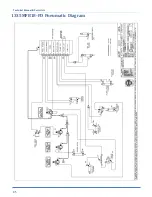
Page 90: ...Technical Manual Parts Lists 85 1335MFB18 PD Pneumatic Diagram 125211B ...

Page 91: ...Technical Manual Parts Lists 86 1335MFB PD Pneumatic Diagram 125696C ...

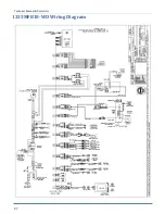
Page 92: ...Technical Manual Parts Lists 87 1335MFB18 WD Wiring Diagram 125212B ...

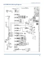
Page 93: ...Technical Manual Parts Lists 88 1335MFB WD Wiring Diagram 125697C ...

Page 94: ...ent upon proper application installation and maintenance AAC Limited Warranty may not be changed or modified and is not subject to any other warranty expressed or implied by any other agent dealer or distributor unless approved in writing by AAC in advance of any claim being filed What Is Covered Electrical components that are not included within the Serial Bus System that fail due to defects in m...

Page 95: ... AAC no puede ser cambiado o modificado y no está sujeto a cualquier otra garantía implicado por otro agente o distribuidor menos al menos que sea autorizado por AAC antes de cual quier reclamo Lo Que Está Garantizado Componentes eléctricos que no están incluidos dentro del sistema Serial Bus que fallen por defectos de materiales o de fabricación que han sido manufacturados por AAC son garantizado...

Page 96: ...Atlanta Attachment Company 362 Industrial Park Drive Lawrenceville GA 30046 770 963 7369 www atlatt com Printed in the USA ...

Reviews: