


D
O
N
O
T
C
O
P
Y
Preliminary
Page 8
•
AP User’s Guide
Atheros Confidential and Proprietary
October 2001
Subject to change without not ice.
2.3 AP Network Attachment and Configuration
AP Network Configuration and Network Boot
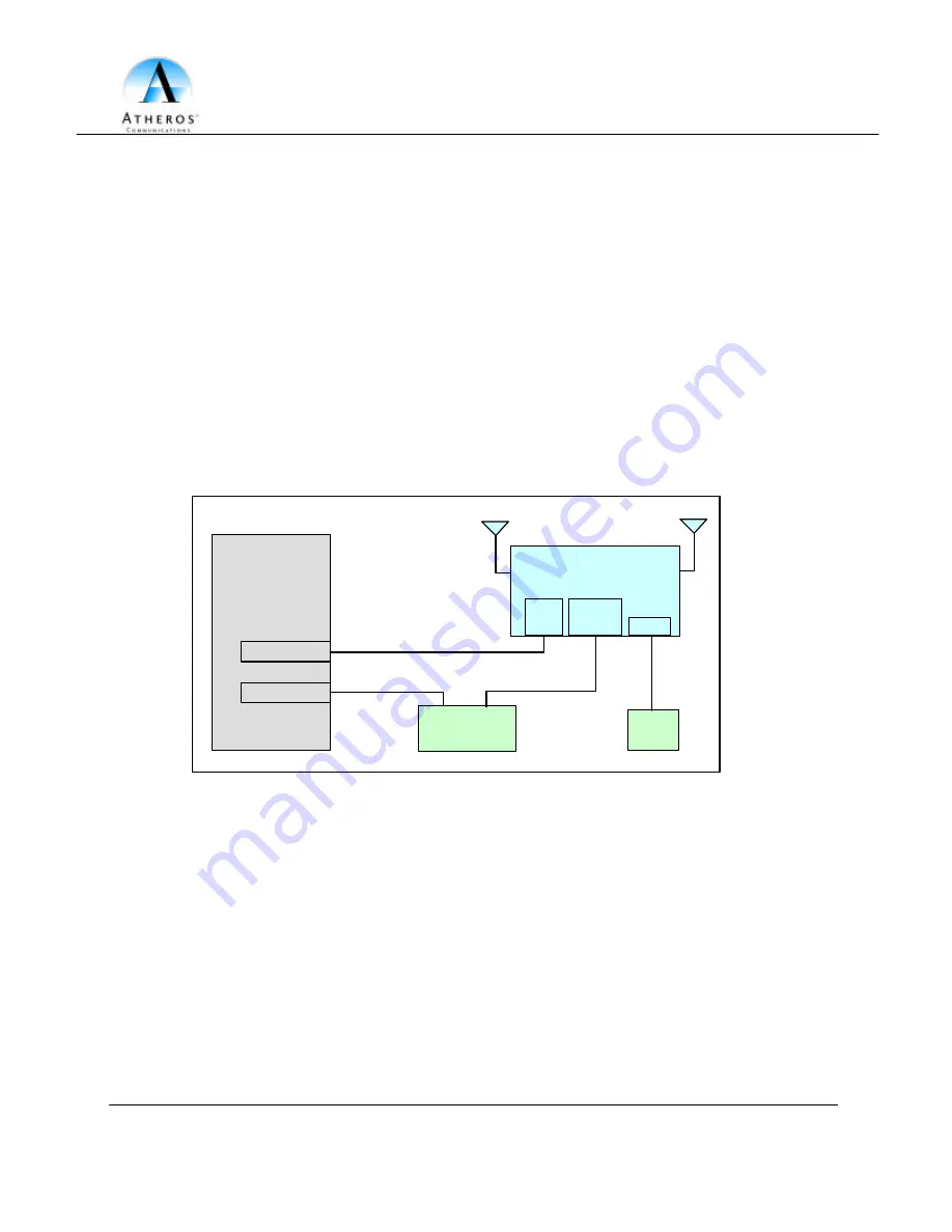
Figure 1 shows an example connection of the AP to a Host PC (HPC). Follow these steps
to establish the physical connections:
1. Plug the serial cable from the AP RS-232 serial interface to the HPC serial COM
port.
2. Connect the AP Ethernet port to the HPC Ethernet card through the Ethernet
hub/switch or an Ethernet crossover cable. An Ethernet switch/hub or crossover
cable is not included with the Atheros AP Reference Design.
3. Plug in the 3.3 V power supply adapter (provided by Atheros) to the AP power
supply connector.
Figure 1 – Connection Between AP and Host PC
At this point, the HPC needs the following configuration steps in order to control the AP:
1. From the Start menu, choose Settings and open the Network and Dial- up
Connections window.
2. Right-click on the Local Area Connection icon, which belongs to the Ethernet
controller that is connected to the AP and select Properties.
Host PC
(HPC)
Ethernet Port
Serial Cable
Ethernet Cable
Atheros Access Point
(AP)
Ethernet
Hub/Switch
COM Port
COM
Port
Ethernet
Port
Power
Power
Supply
Ethernet Cable


