ATEN VE2812EUT User Manual Download Page 21

 Chapter 2. Hardware Setup

11

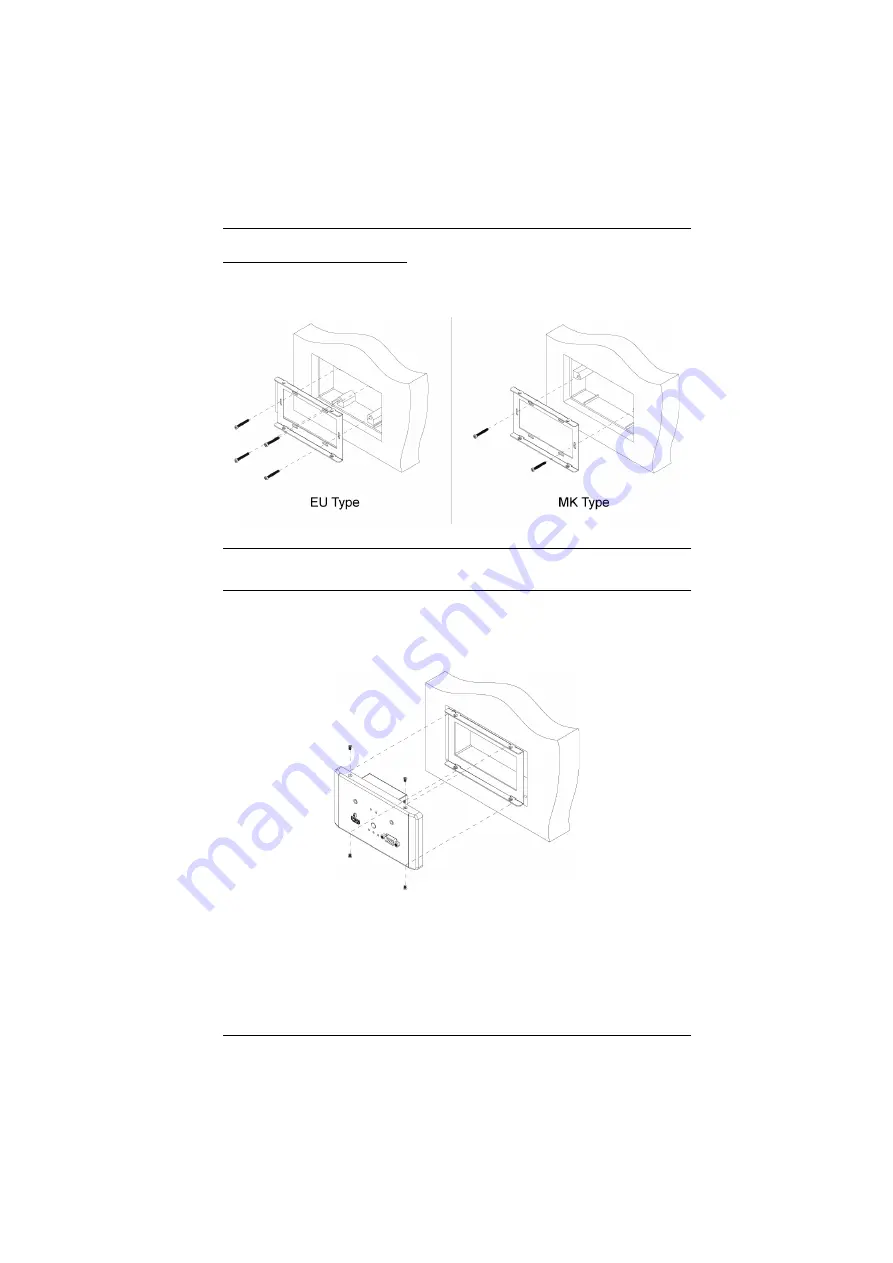
VE2812EUT Wall Mount

1. Secure the supplied mounting kit to your installation site by tightening 4 

screws (EU type) or 2 screws (MK type) to the screw holes as shown:

Note:

Screws stabilizing the mounting kit are not included in the package 
content.

This installation site can be a wall or ceiling.

2. Insert the unit to the installation site and secure it by tightening the 4 screws 

(provided in the package) onto the mounting kit as shown:

Summary of Contents for VE2812EUT

Page 1: ...VE2812UST VE2812EUT HDMI VGA HDBaseT Transmitter with US EU Wall Plate User Manual www aten com...

Page 2: ...sidential area is likely to cause harmful interference in which case the user will be required to correct the interference at his own expense FCC Caution Any changes or modifications not expressly app...

Page 3: ...s prove defective following their purchase the buyer and not the manufacturer its distributor or its dealer assumes the entire cost of all necessary servicing repair and any incidental or consequentia...

Page 4: ...tter 1 3 Pin RS 232 Terminal Block 1 2 Pin Power Terminal Block 1 Mounting Kit VE2812EUT only 1 Faceplate VE2812UST only 1 Power Adapter 1 User Instructions Note Make sure that all of the components a...

Page 5: ...nsiderations 3 Compatible ATEN Video Extenders 3 Components 4 Front View 4 Side View 1 5 Side View 2 5 LED Display 6 2 Hardware Setup Mounting the VE2812UST VE2812EUT Unit 7 Site Preparation 7 VE2812U...

Page 6: ...al vi RS 232 Commands 17 Long Reach Mode 18 Appendix Safety Instructions 19 General 19 Technical Support 21 International 21 North America 21 Specifications 22 Supported VGA Resolutions 24 Limited War...

Page 7: ...t are necessary to quickly and safely set up your installation Chapter 3 Operation explains the Long Reach Mode and limitations and how to set up the input detection mode using the a pushbutton and RS...

Page 8: ...If keys need to be chorded they appear together in the same bracket with a plus sign between them Ctrl Alt 1 Numbered lists represent procedures with sequential steps Bullet lists provide information...

Page 9: ...about all ATEN products and how they can help you connect without limits visit ATEN on the Web or contact an ATEN Authorized Reseller Visit ATEN on the Web for a list of locations and telephone numbe...

Page 10: ...VE2812UST VE2812EUT User Manual x This Page Intentionally Left Blank...

Page 11: ...upporting 3D Deep Color and embedded HD lossless audio formats In addition the VE2812UST VE2812EUT supports Long Reach Mode which allows the device to transmit signals up to 150 m 1080p over a Cat 5e...

Page 12: ...ia a single Cat 5e 6 cable Supports Auto Switch the VE2812UST VE2812EUT automatically switches to a newly plugged in source Functions as a switch and a converter A switch Connects to two source device...

Page 13: ...L 2910 Cat 6 cable for best results The maximum transmission distance varies at different parts of the transmission Compatible ATEN Video Extenders The VE2812UST VE2812EUT is compatible with the follo...

Page 14: ...nnects to the HDMI Out port on the source device 3 Audio In Connects to the Audio Out port on the source device 4 VGA In Connects to the VGA Out port on the source device 5 Input Switch Pushbutton Pre...

Page 15: ...our dealer 2 HDBaseT Long Reach Mode Switch Put the switch to ON to enable the Long Reach Mode For more details on Long Reach Mode see Long Reach Mode page 18 No Component Description 1 Power Jack Con...

Page 16: ...LED Lights green The unit is receiving power 3 HDMI Mode LED Lights orange The unit is set to transmit HDMI input 4 Auto Switch Mode LED Lights orange The unit is in the Auto Switch mode For details...

Page 17: ...t The unit can be installed into a wall box or simply into a recession in the wall Please reserve enough space in the site for the body of the unit The recommended reserved space for each unit is show...

Page 18: ...o secure the unit into the wall There are regional template screw sites and the unit can use the sites easily If you wish to create your own installation sites the dimensions below will help you decid...

Page 19: ...Chapter 2 Hardware Setup 9 VE2812UST VE2812EUT...

Page 20: ...4 screws to the screw holes as shown Note Screws stabilizing the unit to the site are not included in the package content The installation site can be a wall or ceiling 2 Attach the faceplate to the...

Page 21: ...rews EU type or 2 screws MK type to the screw holes as shown Note Screws stabilizing the mounting kit are not included in the package content This installation site can be a wall or ceiling 2 Insert t...

Page 22: ...or a VGA source make sure to also connect a VGA audio jack to the Audio In port on the VE2812UST VE2812EUT unit to transmit audio 2 Connect one end of the RJ 45 cable to the HDBaseT Output port on the...

Page 23: ...se to open the gates 3 Insert the wires into the gates according to the label on the unit 4 Tighten the screws for each gate to secure the wires to the terminal block 5 Attach the terminal block back...

Page 24: ...al can be transmitted Tx to the receiving Rx end of a unit The received signal can then be transmitted Tx to the receiving Rx end of another unit The RS 232 signals can be transmitted back the other w...

Page 25: ...ritizes HDMI transmission if both HDMI and VGA inputs are plugged in at the same time automatically switches to a newly detected input to the connected receiver Note You can disable this part of the A...

Page 26: ...VE2812UST VE2812EUT User Manual 16 Input Selection Pushbutton Press the Input Switch Pushbutton located on the front panel to switch among the Auto Switch HDMI and VGA input mode...

Page 27: ...ble automatic switching type swmode next and then press Enter Task Command Control Input Port Enable automatic input switching swmode next N A N A Disable automatic input switching swmode off N A N A...

Page 28: ...le compromising the maximum frame rate to 1080p 24 bpp 60 Hz via a single Cat 5e 6 cable To enable Long Reach Mode put the HDBaseT Long Reach Mode Switch to ON at either the transmitter or the connect...

Page 29: ...nplug the device from the wall outlet before cleaning Do not use liquid or aerosol cleaners Use a damp cloth for cleaning The device should be operated from the type of power source indicated on the m...

Page 30: ...Do not attempt to service the device yourself Refer all servicing to qualified service personnel If the following conditions occur unplug the device from the wall outlet and bring it to qualified ser...

Page 31: ...uct model number serial number and date of purchase Your computer configuration including operating system revision level expansion cards and software Any error messages displayed at the time the erro...

Page 32: ...ics Control CEC Max Resolutions Distances HDMI Up to 4k 70m Cat 5e 6 100m Cat 6a ATEN 2L 2910 Cat6 Up to 1080p 100m Cat 5e 6 6a VGA Up to 1920 x 1200 1600 x 1200 70m Cat 5e 6 100m Cat 6a ATEN 2L s910...

Page 33: ...4W Environmental Operating Temperature 0 40 C Storage Temperature 20 60 C Humidity 0 x 80 RH Non Condensing Physical Properties Housing Metal Weight 0 29kg 0 64 lb 0 35kg 0 77 lb Dimensions L x W x H...

Page 34: ...Rate Hz 640 x 480 60 640 x 480 75 800 x 600 60 800 x 600 75 1024 x 768 60 1024 x 768 75 1152 x 564 60 1152 x 564 75 1280 x 600 60 1280 x 720 60 1280 x 768 60 1280 x 800 60 1280 x 800 75 1280 x 960 60...

Page 35: ...de a repair service without charge during the Warranty Period If a product is detective ATEN will at its discretion have the option to 1 repair said product with new or repaired components or 2 replac...

Page 36: ...VE2812EUT User Manual 26 Template Printing Please use 1 1 ratios when printing We also recommend using A4 sized paper or larger After printing please measure the print so that the labeled measurement...

Page 37: ...4 6cm 8 34cm 0 80cm 0 40cm 4 6cm VE2812UST Screw Sites Template...

Page 38: ...VE2812EUT Screw Sites Template 12 1cm 6 3cm 6 0cm 0 35cm 1 1cm...

Reviews: